2.91 Already allows selection of BMV for SOC tracking - not sure what they plan to do differently with 3.00 ? Have you tried it?
I have not yet upgraded to it, no. The difference here is that you can have one item selected for the SOC and another for the DVCC. So the BMS can manage the DVCC and a smartshunt or similar can give you the SOC value. If you have more than one BMS for instance the shunt can give you a total. Or if your BMS SOC is not that accurate for instance.
Exactly.
The main problem in the current firmware (and all the way back to v2.20 I think, maybe even v2.12), is that the BMS selection is “under water”. That is a Dutch term for saying it is opaque, the user cannot see what is going on. The system more or less randomly selects a BMS (the details are not that important). In most systems, that is no problem since you only have a single BMS.
In an ideal world, the BMS is perfect and no other means of measuring voltage and/or SOC is ever needed. In a system with a managed battery (Victron nomenclature for a BMS), a single “battery monitor” setting should be enough for everyone. And for a very brief moment, when 2.80 was released, it was so, but it had to be changed back really quickly.
So the new method now is that you can select your BMS for DVCC. That allows two things. It allows using a different device as battery monitor, so the people using a BMV in their systems are covered. And it allows people with multiple batteries to pick which one is the “house bank”. This sort of thing is more typical on boats and yachts (where you may have separate battery banks for thrusters).
Edit: And for backwards compatibility, the old “more or less random” algorithm is kept, so if you upgrade and don’t set anything, it will keep using the same one as now. Reason why I say “more or less random” is because the method is deterministic… it will always pick the same one in any particular system.
Ok I get this part:
4 Batteries and 4 separate BMSs with an overall BMV.
How is this scenario handled?
I want a >0.5C overload protection on each battery from each BMS, but obviously, I’d like the wider system to charge at about four times this rate.
How do I get an overall quadruple setting and still impose singular battery protection?
Can this be achieved using DVCC or do I have to sacrifice a BMS to represent the entire battery bank?
Edit: Or are all these wider parameters covered by the BMV?
Well, whatever battery you pick for use with DVCC… that one will control the charging/discharging/etc. The rest of the banks… up to you what you do.
The typical use for multiple BMSes is where they are completely separate systems. You want them plugged in, so they can be monitored and logged to VRM, but they are not connected to each other, and are considered unrelated to the process of self consumption… for which the system still expects a single BMS (the house battery) to do the job.
If you have 4 banks making up a single battery, then you have to either build a master/slave topology (like most commercial batteries do), or implement a driver in software.
No, I don’t want an all-or-nothing battery bank, if a BMS disconnects a battery the other 3 must carry on.
It’s not ideal but I can live with 1 battery being representative of the state of the 3 others even though they are independent. I’d plan to keep them at the same SOC and be identical units.
This gives me individual battery protection which I want.
But, this isn’t my interpretation of what you are saying.
It looks to me like I need 4 independent BMSs to provide independent battery protection and a 5th one dedicated to informing the system to charge at four times the rate of a single battery.
Which in turn will make it useless for providing single battery overcurrent protection.
I do want the feature that charging is eased off as the SOC nears 100%.
My understanding is a BMV does not have this feature, it comes with a BMS. Essentially this is the only reason I really need the BMS to talk to Venus.
So to have this easing-off feature, and also charging rates suitable for the entire bank, my interpretation is I need n+1 BMSs are required (if I am also going to maintain individual battery protection).
Or do I have it wrong?
Edit: And if that’s the case a BMV is redundant anyway.
Hi @Louisvdw
I am near Rotterdam with Anco Van Bergeijk, close friend of Victron and part of the RS testing team.
He builds a lot of custom batteries as he and his wife run an NGO which builds batteries in Netherlands and installs them in hospitals and schools in West Africa.
I’ve suggested that Anco join EnergyTalk and contribute on this thread as he is a user of your project.
He’s interested in discussing:
- Bluetooth ‘listening’ of individual batteries in a bank being managed by one of your supported BMSes.
- From Anco, “This one needs a little thinking that I didn’t take time for yet. But let’s first keep it very simple. Just showing a bluetooth BMS on VenusOS DBUS would be the first great step and set safe CVL and low voltage limit for when the Bluetooth BMS is no longer connected. For example CVL 55V and low voltage limit which can be treated as DCL 0Amps at 48V. Otherwise just follow the Bluetooth bms cell values.”
- Note that the RS family from Victron will support having a separate battery per inverter. In VictronConnect each RS can have an NMEA2000 instance number set, and that inverter should stop listening to DVCC and listen to that of the battery with the matching instance number (as I understand it).
1 Like
That’s a whole other kettle of fish. I assume you’ve seen the kind of fees it takes to be a member, or to gain access to the official documentation? ![]()
It is not a very difficult protocol to decipher… but it does have this slight political air round it ![]()
I do have a ticket for adding bluetooth which I have not been able to get too, but I am not sure what the bluetooth is to be used for if the battery is already connected to the driver?
I have not yet looked much into the RS range, except that it lookes like it is high voltage based range. NMEA2000 I always just skipped over ![]() .
.
It’s an HF design that includes an MPPT (or two) and boosts the PV directly to the HV rail. There is work ongoing to make each inverter talk to it’s own battery, but at the moment the use case where you have multiple batteries on a shared CAN-bus is not supported by anyone out there. There are some noises from one manufacturer about that… but I cannot talk about it ![]()
In short… way too little is known to do anything at this point in time. But be aware that it is coming.
Happy to lend you one to test with and happy to support the development.
That selecting BMV as battery monitor and using 123bms with your script for DVCC is working great and stable for weeks in my setup. Thanks so much for your serial BMS script.
1 Like
Hi Louis,
Great job with the driver!, I’m very interested in test in my system.
i have a Cerbo GX with the ffirmware version 2.92 Large, and a JBD BMS with RS485 and UART. I tried many times to install the driver in Cerbo, but without succes, also with SSH client. My knwoledge of informatics is not very much but I think I’ve done everythink okey, following the guide. Maybe it’s for the large version?
Hi @Solifoc
The large firmware will work just fine. It is the same with a few extra pieces added.
Make sure all your connections are secure.
Then follow the troubleshoot steps in the wiki
If you still have problems after that post the log files for us.
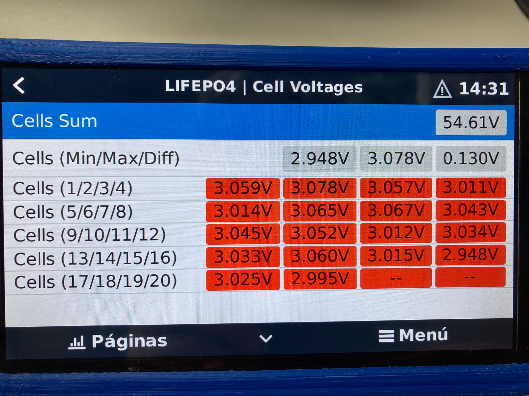
WHAT DOES IT MEAN THAT THE VALUES OF THE CELLS ARE RED? LIGHTS UP SEQUENTIALLY FROM BOTTOM UP
I was doing an update and adjusting parameters, will it be an alarm for low or unbalanced voltage?
[image]
[image]
The cell goes red when it’s balance indicator is on.
If they stay red it could be an issue with that spesific BMS driver. Which BMS is this on?
If that can be, today they are better balanced and the cells in rofo are not so many.
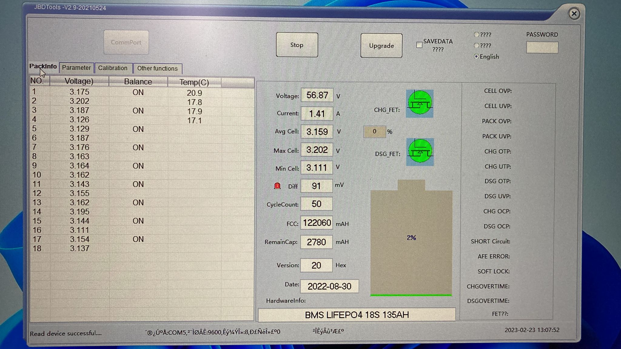
The bms is a bjd, well two because I have a hybrid installation with two batteries, one lifepo4 and the other lithium-ion.
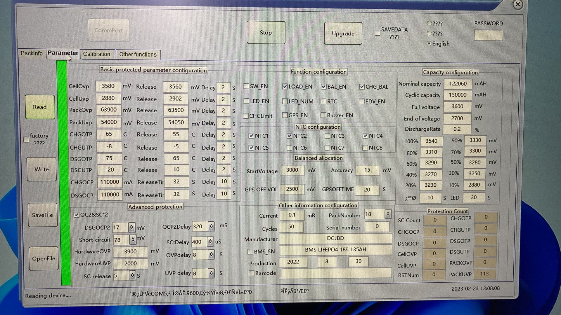
Put photos with the configurations of the two bms
LIFEPO4 18S
ION-LITIO 15S
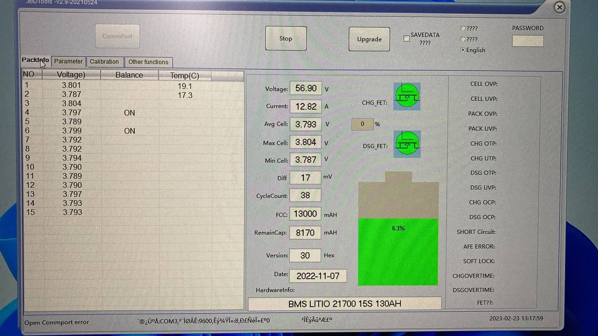
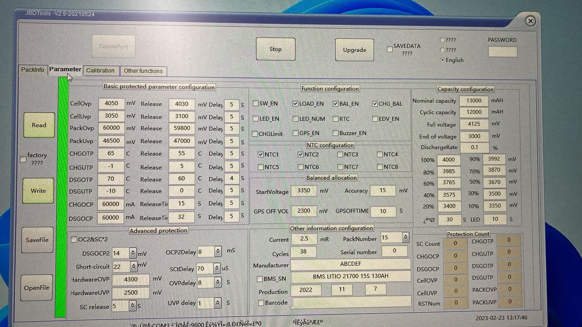
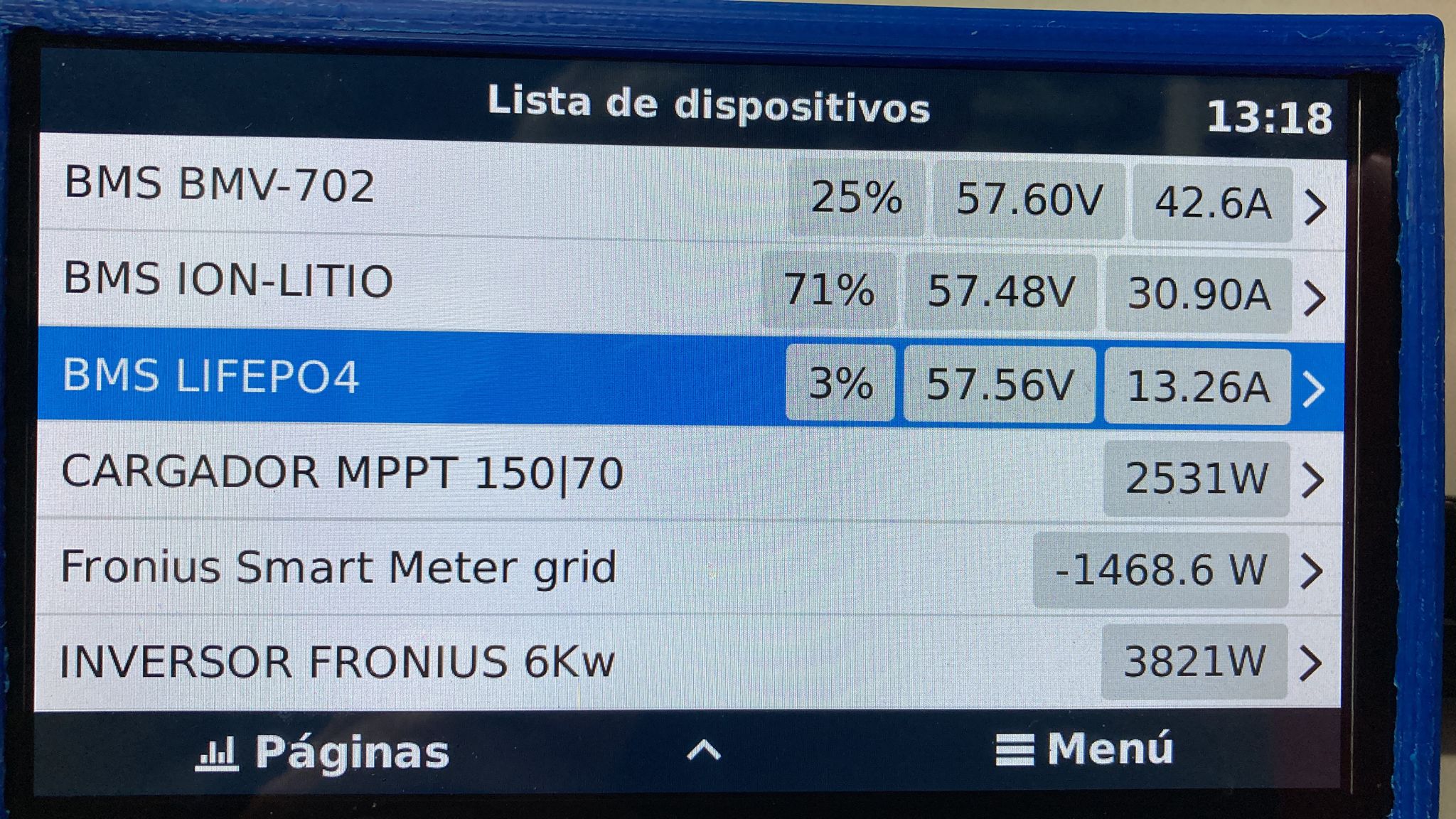
The installation works quite well, charging reaches 64v and discharging at 46v. When it exceeds 60v, the lithium-ion bms stops allowing charging and reconnects when the voltage drops below 60v and something similar happens in the lifepo4 discharge that disconnects at 54v and reconnects when this voltage rises .
In the driver configuration I have set the maximum cell voltage to 4.1 and the minimum to 2.7
The driver version is 14.3
Hello @Louisvdw,
it seems that you were very busy in the last weeks. May I help you with merging the pull requests on GitHub?
Yes, I was out of the office for most of the last few weeks. Should be slowly catching up next week.
Ok, thanks. If you need help I would appreciate to help you ![]()