I’ve created a driver for Victron GX devices (anything running VenusOS, like the Raspberry Pi of VenusGX) that interface with a serial battery BMS(something communicating on RS232 or RS485 or TTL / UART serial). Bluetooth serial does not work yet, as the Pi’s bluetooth is disabled and the VenusGX does not have bluetooth.
You can up-vote for your BMS to be added next in the issue list on github
Currently it works with
JBD BMS (LLT Power / Overkill Solar)
Daly BMS (Daly Smart BMS / Daly Sinowealth based BMS)
ANT BMS
MNB spi BMS - disabled by default as it requires extra libraries installed to work. Contact @Mike Dorsett for information
JKBMS / Heltec
Renogy
Tian Power BMS (Revov battery / LifePower)
ECS (GreenMeter)
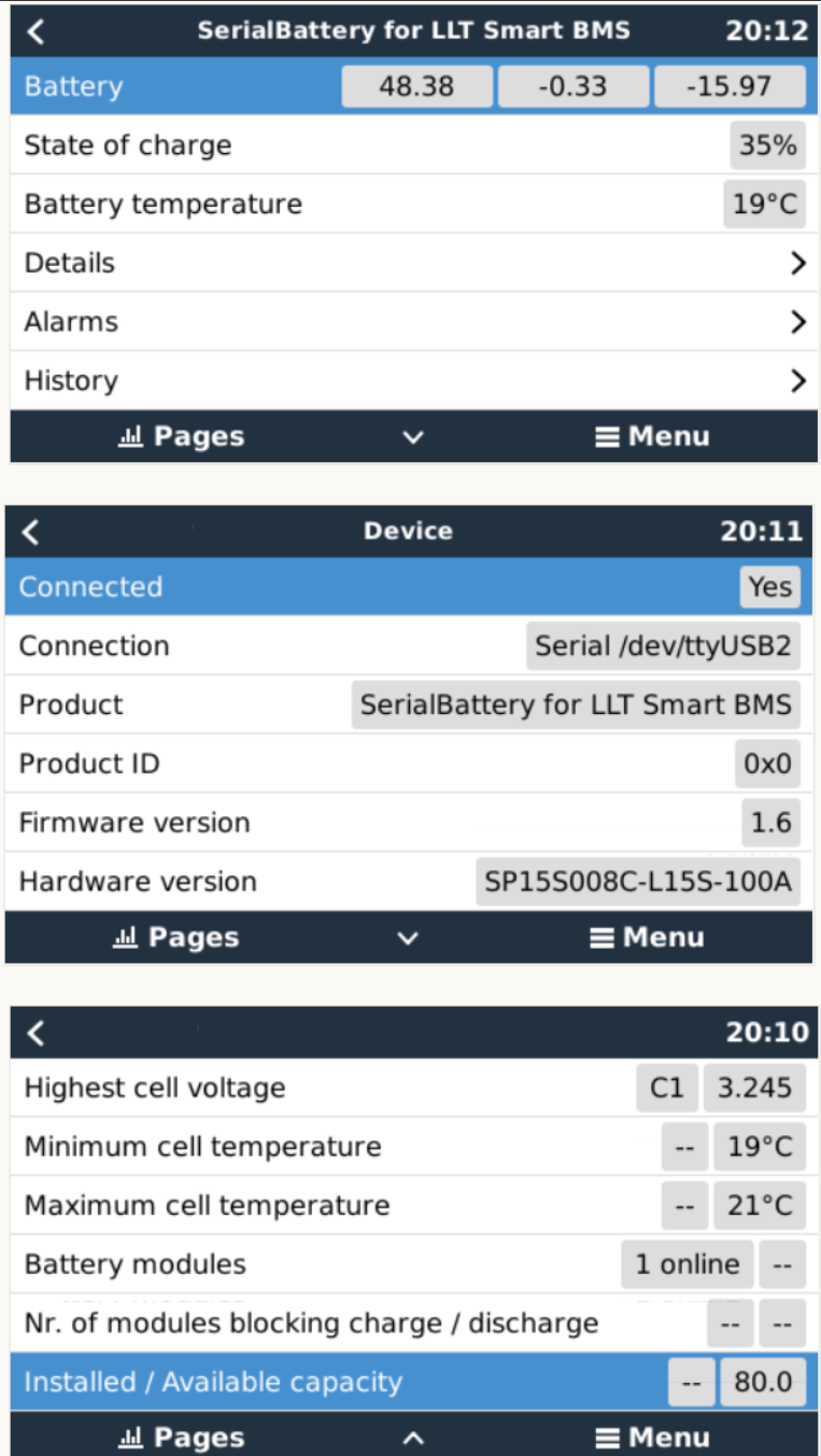
These are the values that is populated in the Venus device from the driver. (This is from an LLT BMS. Other BMS’s might not have all the data available)
Wel, dit is nog steeds in die grense. hahahahaha!!! HHHMMMMmmmmmmm, I wonder I wonder. I got a 3de ANT Smart BMS that arrived after 7 months in slow mail that I want to build in my 3de battery bank. maybe maybe we need to test this.
If you have a Pi 2/3 laying around, then that would be all we need. You don’t really need a Victron inverter, just the GX device (which you can install on a Pi thanks to @plonkster)
Jip!!! Not in the blue side but in the Big Grey side. Hahahahahaha. MLT. And some Microcare Mppts that I’m planning to sell and get a something better.
Can handle any lithium battery cell technology, not just Lifepo4, if I want to change my mind one day.
Has a built-in shunt for accurate SOC measurements.
If I want to buy 280amp cells x 16 later, then I don’t want to swap the BMS.
And if the salient system required values are sent to the Venus, now THAT is a bonus, for I want to set the parameters, just like with lead-acid batteries, not be forced by pre-programmed values.
And my logic says:
Being 200amp, it will idle most of the time.
Up to 260mA balancing.
Can handle up to 85V, so that sorts that teeny titbit out.
Am told that because it has a relay/contactor, that it is good.
CANbus, Bluetooth and UART ports included, so that is also sorted.
Programmable via phone/PC, not that is very good.
And most probably will interface with Venus thanks to Louis and Co - which just makes so much more sense to get one.
And all the above, delivered, for $110.50 excl SA taxes and goeters, who is going to argue.
O, that brings an idea to mind: If anyone else wants to also get one, I can increase my order.
It is a risk, can stand to lose some money, but it is with Alibaba’s Trade Assurance - if that means anything.
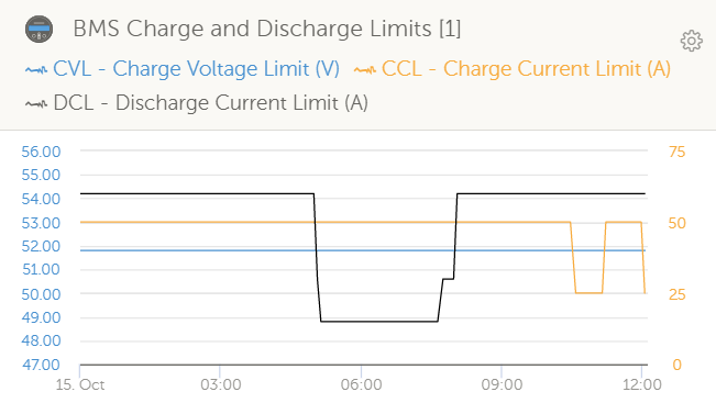
Trialing a new feature for the driver at the moment. Reducing the charge/discharge current limits when reaching the upper/lower limits of the battery SOC.
This is all good and well, just something I want to note: When you enable the option to feed excess DC-coupled PV into the grid, the CCL will be ignored and the MPPTs will remain unlimited. So while many batteries use a CCL, getting the voltage control part right is the most important (in a Victron system at least).
I’m still working on my voltage control function.
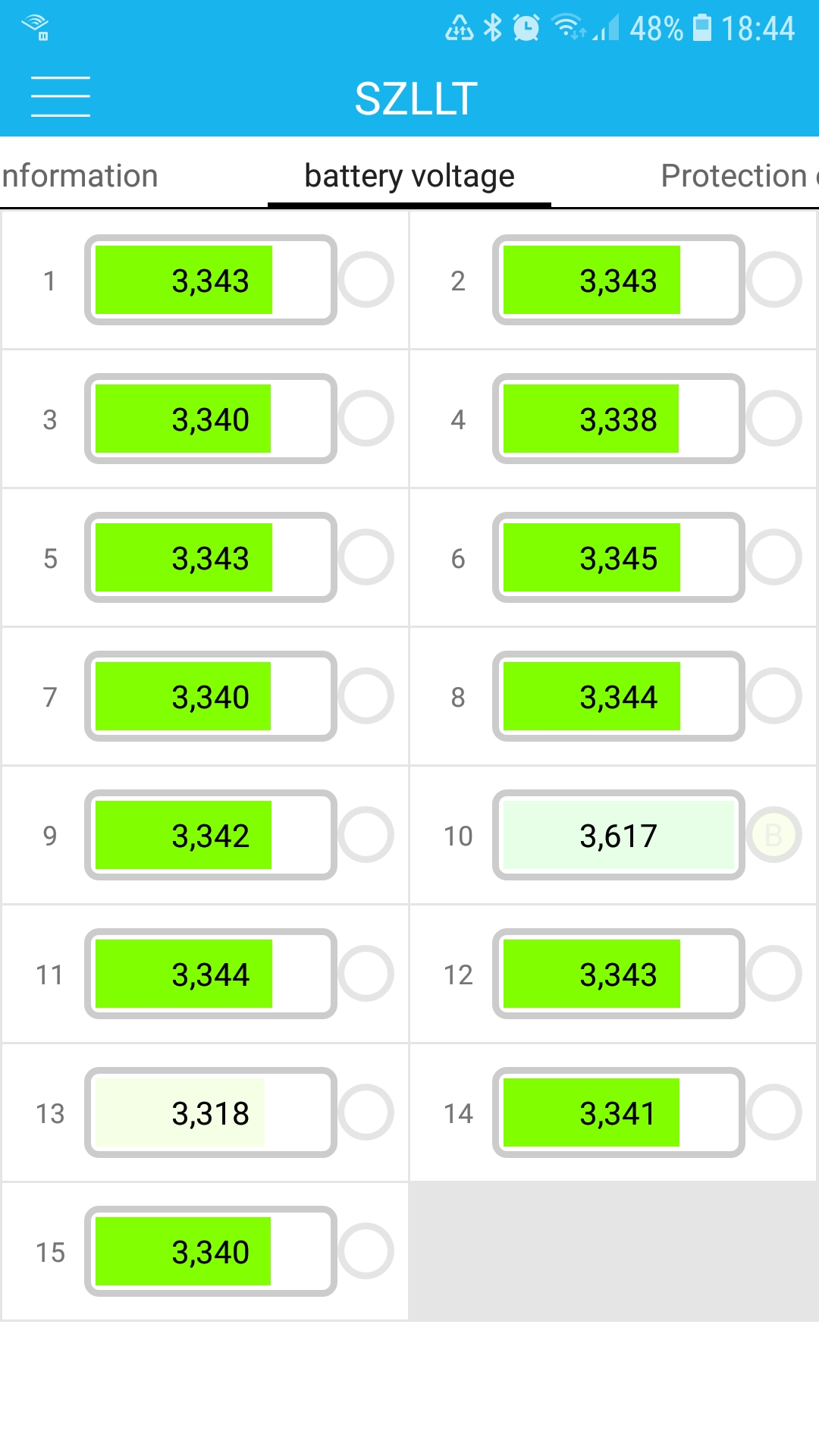
The problem is that I have 1 bad cell (#10) that freaks out while the rest is still at 3.34V and it makes testing my function almost impossible. Once I replace the cell my Voltage control can be enabled for testing.
That’s not necessarily a bad cell. I see this sort of thing frequently with new batteries. After a few weeks, the other 15 cells finally catch up (slowly pulled up at whatever small current the BMS supports). While this is quite frustrating, the truth is also that if the BMS has more bypass/transfer capabilities, you’d be paying more for it… and then use it exactly once (when the battery is new).
That is what I thought initially as well, but it’s been 6 months x 50mA balancing and I can’t see any improvement.
Cell #10 is also only the highest cell after 80Ah. Before that it is just one of the average members. Either a bad cell, or a lower capacity cell to the rest.
Have you tried simply removing the cell, cleaning terminals, and reassembling? This fixed the imbalance issues in my pack. In one case the terminal surface was damaged, so I included a tinfoil ‘washer’ for a compliant mating surface.
You might be surprised by how the tiniest connection resistance affects cell voltage measurement.