Release v0.12 is available
The big changes are for fixing issues experienced with the driver on 2.80/2.90 firmware interfering with other devices, Tian/Revov BMS support and fixes for Daly BMS values.
Release v0.12 is available
The big changes are for fixing issues experienced with the driver on 2.80/2.90 firmware interfering with other devices, Tian/Revov BMS support and fixes for Daly BMS values.
OK, so with the latest driver version, we can safely go with the latest or newer Venus than 2.73?
One more thing - are those Qucc BMSs supported?
They seem to be like JBD despite there are no jbd model labeling (like in overkill solar)
Yes you can go to newer venusos firmwares now.
QUCC are just relabling other BMS.
This one in you link is a JBD (the app is the give away), so it will work.
I have another QUCC here that it actually an AXE BMS that is not supported yet, so you cannot go by QUCC in general and need to make sure.
Someone advise on BMS calibration. Is it needed to be performed in general, how to understand it is needed to be done or it is best to do it anyway during initial battery build?
I am doing exactly that now and charged the pack (16x105Ah LiFePo4) to some stage with the first BMS I ordered (not supported by the driver) and now I will change it to finish the charge with the JBD-SP25S003 (16s, 100A) which I plan to use as final in the system with the driver.
I am curious whether to perform the voltage and current calibration at this initial “on-bench” stage and does it worth doing that with the potential of screwing something up. ![]()
I don’t suggest you do a calibration. Rather keep it as it is. If you don’t compare this with something it will work great.
Your BMS will be calibrated already and that should be good enough.
If you are someone that like to squeeze every last 0.01A out of your 10 000Ah battery then by all means go ahead. (but then you should have bought that $10 000 BMS instead of the cheaper option ![]() )
)
The JBD is one of the better options so I would not bother. Rather put more effort into making sure your cells are all well balanced.
For that, on the JBD your will find 2 balance settings. Balance Enable & Charge Balance
Balance Enable should be ON.
(I cannot remember exactly which way the Charge Balance should be - you will have to check)
In the one Charge Balance setting the cells are ballanced only when they are being charged and the other way only when they are being Discharged.
Normal operation you want to ballance on charge only or else the cells will deplete when just standing there, but this is a great option to do that balancing before you install the battery. Charge the battery up to full capacity - you might see some cells being high and other not - just stop when the first one reach cut-off, switch to balance in discharge and leave the Battery for a few days. Every day or two you can top up it again until you see they are balanced. The close to balance you start the shorter time this will take.
Just remember to switch the Balance on Charge only before you start using the battery
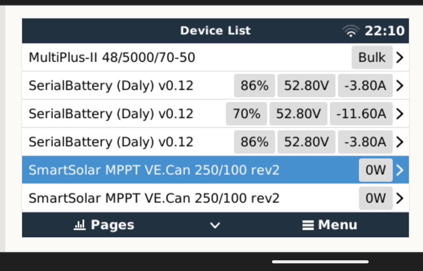
Hi, i have make some progress and now i can monitor 3BMS eqch connected by usb to hub.
One is 135Ah and two 105Ah battery setups. Driver can set capacity i remeber and becuase i use at first one 135Ah i set 135Ah now on rest 105Ah says capacity 135Ah available 105Ah it means Daly send capacity what is set in BMS. In deiver set 0 to get real from BMS for each connected battry setup?
Related to @Janekx concerns, I am also wondering what is the purpose of the so called “Cycle capacity” in JBD which they recommend to be set to 80% of series cell design capacity (t.e. for 100Ah cell to be set to 80Ah). According to the description this parameter is used to calculate the state of charge of the pack.
I can imagine that if you set your charge/discharge voltages (in the charger, Multi, and the GX driver) so you can use around 90-95% of your battery capacity, if the BMS report this cycle capacity parameter (80% capacity) to the GX via the driver, those values will be interpreted by the GX either not letting you to use the desired high capacity, or simply the SOC information will not be correct.
Can someone reveal the mystery (probably due to my confusion) around this and whether it has some result on the system operation.
Is it good idea to set this either the same as the design capacity or the capacity that you are planning to use?
Strange behaviour. The lowest BMS is 135Ah others two 105Ah. One will think it is get quite same power from each of batt and voltage seems like but SoC says too big diferent.
Im experiencing issues with other ve.direct components on venusos 2.87 with version 0.12.
the serial rs232 ve.direct disconnect all the time and get picked up as random/wrong serialbattery bmses.
is there any way to force serialbattery to only use a specific dev like /dev/ttySB and not try and open all my ttyusbs?
i map my bms though a udev rule and would like the driver only to use this device and ignore all others.
I am now testing the battery pack (still "on bench test) together with setting up my R-PI GX with Venus OS v.2.87 . Managed to get the serial-battery driver working and I now see the battery pack details in the GX. Thanks to @Louisvdw for his efforts and fantastic work.
I can suggest two options, I think they can be easily integrated:
About the calibration - when I installed the BMS at first it was not showing the current accurately enough - there was around 0.5A deviation and currents less than 0.4-0.5A were not even displayed/measured.
The only thing that I did was to do the zero/idle current calibration ensuring that there are no consumers first of course. After that, I can say this JBD bms provides pretty accurate measurements.
The voltage readings are around 2mV above the real values (comparing with readings from high precision battery tester), which is perfectly OK
When you buy lithium cells or batteries they are rated per cycles they can work. So many will rate that the cell will still give 95% of full capacity after 2500 cycles or give 80% capacity after 6000 cycles. you can use this to estimate the life duration you can expect from your battery. If you do a full cycle each day then the battery will last for around 6000 days or 16.4 years.
The cycle is calculated using the cycle capacity or something similar. So if your cycle capacity is 100Ah and you discharge 60Ah the one day and another 40Ah the next day then that will be 1 cycle.
This is something your BMS calculates and the driver will publich the cycles under the History section of your BMS, but the cycle capacity is not used by the driver.
Set this as the capacity for the cells.
The driver or the BMS does not have any capacity to limit or match the current draw when you use multiple batteries. It is a factor of the resistance and voltage of the battery.
I guess the easiest way to think about it is like water tanks with the higher capacity battery like a taller tank which has more presure and so will supply more water when it is full.
You will have to look at the log files. First the log for the device that get dropped and then for the same port on the serial bettery that gets picked up. It could be that the device responds to one of the battery commands that the driver support.
I have created a video to guide new users installing the driver. Hope it will be useful.

Nice.
I see a python bytes object that got stringified for the firmware version. Probably need to look at that.
Don’t get me started on the number of bugs I had due to that little change in python2->3 ![]()
Yes I know about that bug. Will get to it eventually ![]()
Continuing the discussion from DIY Serial battery driver for Victron GX:
Hi,
I’m new here ![]() , thats really a great project, I’m planning for a 16S Battery at the moment, would a JK B2A24S20P BMS with RS485 be supported with the drivers? CAN-BUS would not work, right? If I want to extend the battery at a later point in time with another 16 cells would that also be supported? Thx Stefan
, thats really a great project, I’m planning for a 16S Battery at the moment, would a JK B2A24S20P BMS with RS485 be supported with the drivers? CAN-BUS would not work, right? If I want to extend the battery at a later point in time with another 16 cells would that also be supported? Thx Stefan
CAN-BUS will not work, but the RS485 connection to the JKBMS and the driver does.
I have a question/remark regarding the ‘midvoltage’ calculations and readings. In the display I see a ‘top section voltage’ and a ‘bottom section voltage’. If I take both and calculate the midpoint deviation, I always get a different value than what is shown as ‘Mid-point deviation’.
In the code the midpoint is calculated as (top-halfvoltage+bottom-halfvoltage)/2. This makes sense. But then (what I think from reading the code), this midpoint is taken as the displayed ‘bottom section voltage’ (which would be wrong!) and the ‘top section voltage’ is calculated from battery-voltage(read as whole battery voltage from the bms!) minus the midpoint value, which would also be wrong.
The whole idea of midpoint voltage deviation measuring and display comes from lead acid battery (telecom 24V or 48V) systems where it was meaningful to have an additional voltage input to get an idea if the upper 12V battery block(s) deviates from the lower one(s).
Here we have readings for every single cell voltage and at least for me the display of these values is not very meaningful.
Hope to get your opinion about this.
Best regards, Jörg.
Using the Delta, as per the BMS, is extremely important for me as an indicator of a problem brewing quietly. Midpoint, not so much as the Midpoint calcs can be tricky as you say Jörg.
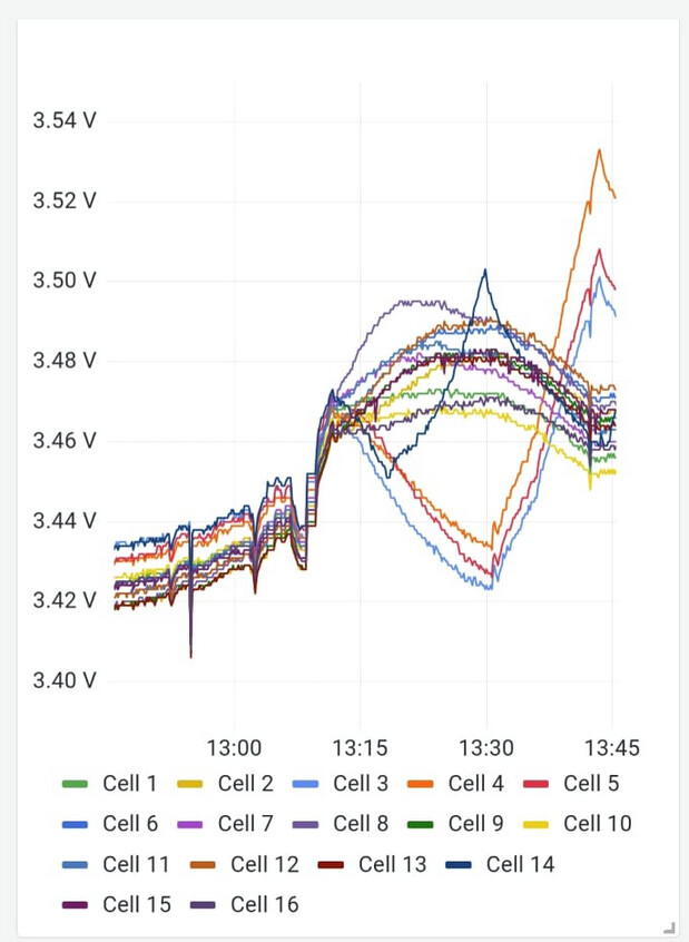
When the Delta is too high, say 0.100v, one looks at the data per cell and if you have data like the pic below, it becomes very handy to see each individual cell’s voltages, even more so if the data is over time.
Let me share what I saw yesterday. This data goes back 6-8 weeks (new install), and consistently those 4 cells did that as per the graph.
The lowest 4 cells never really got “charged” over the period because the system throttles back the charge amps on SOC, SOC being volts linked, leaving the lower cells behind all the time.
Over time this is aggravated as these 4 cells never really got the proper “charge time/amps” yet when discharging they carry their part 100%.
On the graph, one can see where these 4 cells were individually boosted, hence them “shooting out” on volts. Once done, the system is left again for a few days checking the graphs per cell, to see if they are better.
So volts per cell, the BMS Delta the warning, becomes quite an important piece of info to ensure the cells stay as close as damn, together, when charging.
Yes, I know what you are talking about. I was also against implementing it initially. This graph will really only make sence under a magnifyer if you are using lead acid batteries. For lithium batteries that use a BMS the min/max cell graph is what you need to look at.
But some people feel they can get some value out of the midpoint graph using lithiums as TTT mentioned, but that is just as a quick glance overview if there might be a problem. (You could see the same in the min/max cell graph but those values are smaller, so you have to look harder ![]() )
)
So in the Venus system how that is input is a battery total voltage and a midway voltage which the driver simulate that using the cell voltages.
It gets more interesting if you have a battery with odd number off cells like 15. Then the last cell’s voltage get divided between the 2 halfs, which means you will never see if cell 15 has an issue.
The better option is to look at the min/max cell voltage graph and disable the midpoint. That is what I do ![]()