3rd Group Buy - Grade A Fully Matched Lifepo4 Cells

18 cells at nominal 3.2V per cell is 57.6V and closer to 62V when full.

Of course you can run your cells at lower voltages, but then you’re losing out on some useful capacity, so I’d push to at least 62V. That is of course no problem for a Victron setup.

You’d need a BMS that can handle more than 16 cells AND that will balance below 3.45V. Some BMSes only close the bypasses above a certain voltage, as it is usually pointless to balance lower down.

The new thinking is only to live the plateau of the charging curve.
Apparently, it’s better to avoid the potential decrease in longevity that may be caused in a cell as voltage rise that comes very quickly for the sake of a few per cent extra capacity.
Certainly, with an extra two cells, you are more than getting what you may lose back.

1 Like

I get that :slight_smile: I agree that people pushing for 3.55V per cell (or even higher!) do so at the risk of shortening battery life, and for very little extra capacity. It comes down to what voltage you consider the elbow point. In my mind this voltage has always been 3.45V per cell, or at least 3.4V.

Interestingly, the BSLBATT battery that is sold by GetOffGrid (and now fully supported in Victron systems) have a 54.5V charge voltage, with 16 cells, which means about 3.4V per cell. And I was really impressed with that battery…

So 18 cells at 3.4v = 61.2v, so you agree, very cool thing to try?

1 Like

Oh absolutely, just make sure you have a BMS that balances around that point.

I have one concern left. Maybe. Which is just that on the flat part of the curve, you actually don’t know if the cells are balanced. They may have a similar voltage, but because they are on the flat part of the curve, they may differ somewhat in their state of charge. That might be another reason why you need to take them at least towards the elbow point, if not above it. But again… you can fit 18 cells into 63V (18 * 3.5V), which is not too high to make this work…

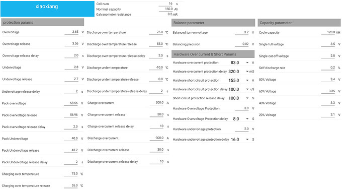
Look at all the settings one can adjust …

So you’re fine then… but don’t expect to buy some random one and for it to just work. Like last time, né?

Once burnt, twice shy … so far, with me and all my dramas, with now 3 of these BMS’e, 12v 24v and 48v, I have not had ANY dramas at all … a HUGE thanks to @Louisvdw software too.

I’m running at 3.5v, once the cells are balanced. :wink:

So now I’m thinking, 280ah x 18 cells at 3.5v … why not … @Phil.g00 the one who started this! :laughing:

Hmmm so should I change my Pylontech bank’s charge voltage from 52.4V down to 51.75ish?

I better expound on this opinion.
In the beginning, people were doing what they were told, and reputable battery suppliers were only working with professionally matched cells. More and more though there has greater experimentation and through that a better understanding of these cells.

Let us consider a single cell:
If you drew a very thin line on an overhead transparency slide representing a single cell’s charge/discharge curve at 10 deg C and overlaid another slide representing the exact same cell at 30 deg C. Then that your settings would be governed by the inside of the flat portion of both curves.
(I accept that both limits may be covered by one of the two slightly different curves.)
In this instance, you would be able to tailor your charging settings to get the absolute maximum safe capacity out of a single cell.
But a battery bank isn’t a single cell, it is a bank of cells in series.
Now your cells may indeed be matched, but I doubt absolutely perfectly matched. So let’s overlay another 15 pairs of slides on top of the first two.
Offset each pair of transparencies half a millimetre to all points of the compass.
Now, that once thin line becomes quite thick and blurred and your charging range is again shortened to the limits of the flat of the blurred plateau.
But wait there’s more ( as they say on late-night TV)…
People have sought to find cheaper solutions, as they do.
People have been knowingly (and sometimes unknowingly) been taking advantage of cheaper un-matched cells. ( Still new, but sometimes $40 per cell cheaper). Now that overlaid charging line is thicker again and that flat portion has to have an even more conservative margin.
So further capacity is again apparently sacrificed.
But, at these cheaper prices, people have started building 2P 16S, 3P 16S and 4P 16S banks.
Thereby increasing their banks’ capacities again, and they also don’t want to go to the expense of a BMS/16 cells, so they take advantage that the charging line doesn’t actually get thicker indefinitely.

The trade-offs now become worth it to have more conservative settings, a greater bank capacity and still enjoy battery longevity.
Now, my argument is at these more conservative charging settings, one can afford to have 18 S banks, with Victron equipment that can charge up to 60V.
Once, I had formed this opinion, I found that some people ( other internet DIYers) who were already advocating this approach had implemented it and were not seeing any disadvantages.

In my own experience, I have had a bank of 4S 12 V Silver Calcium LA batteries, which charge at about a volt/battery higher than standard LA batteries, so I know the reliability of Victron equipment isn’t adversely affected by this non-standard higher charging range.

1 Like

And then there are people who go for premium cells, a configurable BMS, and then don’t have to go 2p, or 3p … thanks to all this new knowledge being shared by more knowledgeable people.

If @plonkster is happy on the Victron side, @Phil.g00 happy on the cell side, then I see no reason why not to go 18 cels. I can even drop the volts down from 3.5v If that makes any difference.

My goal is to settle on a bank and forget about it for many many years.

Will that ever be possible with DIY? If you get that right, please let me know how!!! Dit jik mos altyd waar dit nie moet nie…

No, because the PT balancers only start working properly at 3.485V per cell. There is a reason for the increase in the charge voltage, from 52V to 52.4V. Technically (if you follow the pylontech spec sheet, 52.5V is the lowest you should go).

If you scratch that, the itch will just grow.
I am trying my very best to stay with only my 2kW solar panels and not looking at anything that is posted in this thread and the enormous numbers @Ironman posted :face_with_thermometer:

Balancing is another debate. Top balancing, bottom balancing people have opinions. If you balance at the top, then expect a greater mismatch at the bottom, if you balance at the bottom expect a greater mismatch at the top.
Personally, I think you should balance at neither extreme, because it is at the opposite extreme that mismatches cause damage to cells, and that opposite extreme mismatch is now exaggerated.
I think you should balance your most common operating voltage, that way you’ll have the the cells balanced most of the time and also reduce the mismatches at both extremes.
This approach goes hand in glove with conservative top end settings.
If you really want to build a big bank and nail your per cell settings try one of these:

I bought 1, I think they are good value if they work. I don’t know yet, thanks to COVID mine is still unboxed and unused. (I think there is a little brother for cheaper, I just didn’t want to spend a lifetime balancing cells). Calculate the length of time, it would take for the balancers of a typical BMS to balance out cells initially, after a charge and discharge on a lot of 280Ah cells.
Anyway, factory balancing will just pairing cells with like curves, and I still reckon I could optimise the configuration in any #P 18S bank by really paying attention to the curves.

If you get the above there is probably no need for this cheap and nasty ballpark cell internal resistance tester: But this is a quick indication of cell heath.

If the cells vastly differ, I take them all to 2.8v.
Recharge them at 3.45v to full.
As the volts climb, I use “The Bulb v2” to “help” balance even faster.
Discharge normally, recharge x 2-3 and the bank is ok.

And then DVCC Max Charge Volt limiting came about. Now the above is even easier.

Takes 2-4 days on cells that are really unbalanced.

Alternative, just leave the bank on a lower voltage for charge, walk away.

This is my point, at slightly more conservative settings you are losing very little capacity and gaining a whole lot of peace of mind. Ideally, the conditions shouldn’t be that close to the bone that the BMS has to work in anger.
Of course, it sounds like some manufacturers (like Pylontech), feel they know better and they probably rightly so for the vast majority of users.
Then again I have seen enough forum queries from users as to why their Pylontechs jump from 88% charged to 100% charged.
This leads me to believe that there isn’t actually 12% capacity left on the table but that Pylontech is running very close to the upper charging kneepoint, where the voltage shoots up for a very little further charge.

Mine too, I think I’ll be a little bit more conservative at the top end.

1 Like

Yeah, I can make that happen easily my side … one cell out of whack, its volts shoots up and wallaaaa … 100% SOC … and BMS is angry. :laughing:

What would you do with 18 x 280ah Eva cells ito settings?

My case is different to yours. ( I am going to have cells in parallel and in series).

So I’ll talk about what I think yours is - just a single series bank.

I haven’t bought an EVE cell with all the certs and charge/discharge curves, but it sounds like those documents are supplied in your imminent purchase.

So, If I was you, I’d look at all the curves and determine the base voltage of the upper knee point of the single-cell with the lowest upper knee point.

(The cell most likely to be damaged first at the upper charge voltage - I hope that makes sense to you).

And then multiply by 18 to determine an overall max charge voltage.

I would repeat the exercise to determine the highest knee point base of the weakest cell and also multiply by 18.

(The cell most likely to be damaged first at the lower charge voltage).

This will determine the overall low end cut out charge voltage.

Then apply a small safety margin at each end on top of that.

I have a gutfeel this may result in a max cell voltage just shy of 3.4V, but don’t hold me to that, the curves will decide.

In my own case, as I have the test equipment, I won’t just work from documents, I’ll determine the curves for myself. Or at least do some random cells to determine if I can trust the documentation.

If I can trust the documentation, I’ll do the same thing, but added to it I’ll pay attention that any cells I parallel will have as near as dammit identical curves and internal resistances.

If I can’t trust the documentation, or think I can benefit from doing my own curves I’ll do my own curves.

I’ll reject any outliers.

Again from the mean of the curves, I’d guesstimate my most probable daily operating voltage and initially connect all cells in parallel and balance them at that voltage.

Possibly as years go by, as hopefully, they should, I might test a random cell to determine any drift.
2 Likes

I have wanted to turn my pack into a 9S pack quite some time now, being on a 24V Multigrid 1 extra cell will essentially drop my DC current by 12% and give my little 100/50 MPPT a little more max power throughput.

My only problem is, I have noticed with my 8S pack if the BMS disconnects the battery voltage shoots up to ~30V
So I am affraid that a 9S pack at say 3.5V cell would easily push me over the 33V input limit of the Multigrid, your thoughts?