@plonkster is this an option to even consider?
My case in point.
When you had these ripples did you have a dumb BMS that had not comms? (the Daly days)
Did you use the wrong settings? (the BMV days)
Or did you use a BMS that is connected to the management system. (what you have now)
But I do get the point for if you have this monster battery and it disconnect it can cause issues.
It wasn’t even the missing comms that was the problem. The BMS simply didn’t have the right specs, to allow some room at the top, or that is how I understood it.
I like the way BSLBATT handles it. Charge voltage on a 16-cell is 54.5V. That’s 3.4V per cell. Nice and low. But… the BMS leaves you lots of room at the top, you can push that thing to the other side of 58V before the BMS intervenes. Now in this battery, they also have directional control, so when it intervenes it blocks only one of the directions… but… even if it didn’t do this, the combination of a low charge voltage and plenty of room at the top… makes this battery a winner in my opinion.
I deduced in the end that the Daly caused the damage to the cells.
At the time no-one “knew” what was happening, @plonkster did deduce it was cell imbalances, but I could never measure 16 cells fast enough.
I did control it with lower voltages as per @Gman help, and keeping FAR away from +95% SOC. Tough one I tell you.
When I got the new big BMS, that is when I saw what was happening per cell, which even the big BMS had drama controlling, “The Bulb” was a huge help at the time. At least it beeped when cells went out of whack … that happened a lot at the time.
The joke is, this NEVER happened on discharge ever, nor charging. It ALWAYS happened above 95% SOC, <300w AC loads, when the cells “lose it”.
FWIW, also to ponder on, I see right in front of me, as I’m watching charging 57 x 280ah cells, that if you set a Victron inverter to Keep Charged, it “leaks” some charge to the cells all the time once the bank hits 100% SOC.
And if you set it to 100% SOC, and the Grid Setpoint is not set to Zero, it also “leaks” some charge back to the cells the whole time. I set it to zero, so it slowly discharges once it hits 100%.
I tried to set the driver to like 0.1 charge amps, but as we saw, you knew, you cannot stop it.
Both the above, if your cells are not spot on all the time, gets interesting, and over time, as the cells get “older”, who knows what people will find.
To add to this… it might be a bit premature to discuss “the best” voltages. It is going to depend on the capabilities of the BMS. If the BMS allows balancing low down, you can go for 3.4V per cell (I would not go lower). So 18-cells wide, that’s 61V. You try that for a week and you monitor things. I would go as far as deliberately leaving a cell slightly lower to see how the BMS handles it.
If you are not happy with the results, go for 3.45V. Find the lowest voltage that gives good results.
That’s called R&D. And that’s probably why the brand names are a bit more expensive too 
Your battery is the capacitor for the system. It should do the leaking so that you don’t get the ripples.
1 Like
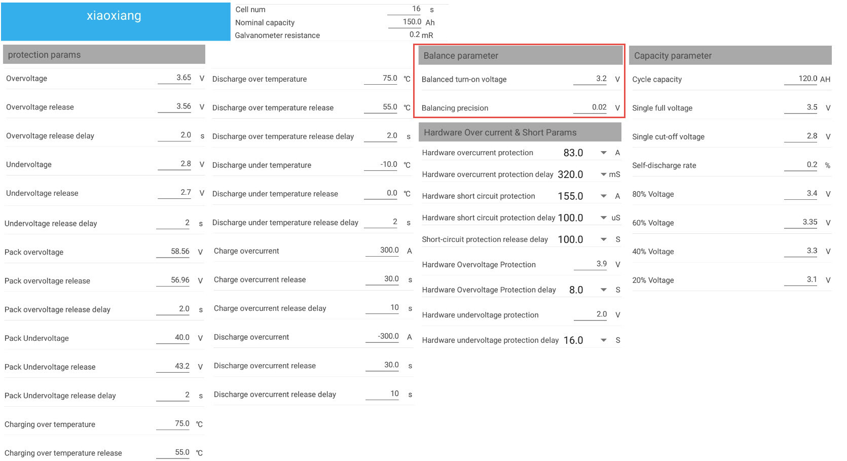
I have a BMS and 18 cells to test yes.
Can set the BMS balancing turn on and precision. And one can set it for charge only or charge and discharge.
Here are the options I have … and I have tried it. 
Exactly. It has some “weight” to it, as I sometimes say. It is no surprise that the BMS disconnected above 95% SoC. It was “protecting” the battery against what it thought was too high a voltage. Once the “weight” is removed from the system, it becomes easy to shake the rest of it around (aka DC ripple).
Try starting at 3.35V. I think below that, you’re too much on the “flat plane” of the LiFePO4 discharge curve.
And therein me staying f…ng far away from anything near 3.65v charge voltages as some of the YouTube vids say. Bugger me, they’ve seen shiite. 
3.55v on these new 280ah cells, it gets into balancing fast above 90%.
3.5v is better
3.45v is cool and smooth - but then the EV-Peak takes DAYS to “finish” them off.
R&D, the tablet, the PC, the cells … all right in front of me the whole time to see what is potting.
And it is taking a hell of a lot of time … bugger me … but once I’ve done this exercise …
That setting is for the existing “Frankenstein” bank … it works to keep them older cells “in line” going up and down, as I balance going down too …
On the new 280ah bank, once installed, I will do so!
Although I fully understand that … I really want someone to show me the settings to ensure this does not happen …
This is a valid question.
I see the problem as being a high voltage disconnect that doesn’t allow the load to discharge a fully charged battery.
This could mean an inverter shut down for an extended time because only pee-wee balancers can burn off the excess voltage, not the load.
But:
Maybe the issue is resolved by sensible lower charging voltage settings.
Maybe the issue is resolved by using balanced cells.
Maybe the issue is a non-issue because multiple banks are used.
I think a little more time establishing if the issue exists is warranted.
1 Like
Slightly of topic, but still op topic in the the grander schemes of things!
When running 18S, the Charge Voltage will be higher, and the current less. Does this means that your MPPT can give more than the rated specs?
IE Victron MPPt 250/100. 4800W max charge at 48V, but with 62.1v x100a = 6210W
Or am I looking at it wrong?
There has been some recent discussion about active balancers, and the ability to selectively balance on discharge or charge or both.
- I think balancing should only be done whilst charging and only at the high end of charging voltage with small currents.
- I think the higher current balancing capacity of an active balancer only has its place in initially balancing the pack. And as such should not be a permanent bank attachment.
- I think that an active balancer that is allowed to balance on discharge is inefficient and will actually result in cell unbalances.
I think that you may have inadvertently exaggerated or created your own problem.
Rarely, I ran the 400m track event at school.
I always picked the outside lane because I got such a big headstart on everyone else.
But I never did win.
You see every lane had its own curve, and you could never switch lanes. They had laid out the track so that every contestant ran 400m by the finishing line.
Those lanes are like the different charge/discharge curves of different cells.
Think about running that same 400m track but instead of running from the staggered start to the finish line. I want you to picture walking slowly from the finish line to the staggered start and then running as fast as you can back again to the start.
Every contestant in their own lane would still have travelled 800m and if they all ran at the same speed they would all finish together.
Now, let’s take this a step further.
Let’s add a big ass active balancer as I have heard proposed.
Balancing if set wrong is like allowing lane changing in my race.
So you balance your 280Ah batteries whilst discharging at 0.1C at up to say 5A.
You have 5/28 = 17.8% balancing capability over a fairly long discharge period.
Great, you get to 25% SOC and are perfectly balanced.
Whoop dee doo.
Now, what happens when you recharge?
Well, now that balancer has to “undo” all the balancing it did on the discharge.
But, here’s the issue. I charge at 1C.
Now I have 5/280 = 1.78% balancing capability over a 10x shorter charging period.
And the balancer is not able to totally undo the mess it made during discharging.
I hope my analogy makes some sense.
1 Like
And this is where there Smart ant bms works nice. If the lifepo4 bank starting to get full and there is a cell that is going over the settings that I program in to the unit, then Charge part of the FITs open so it doesn’t take charge but the Discharge FITS stays close so the inverter and mppt still gets power. You will see that the Cell Difference Balancer is running. It balance at 200ma. The Charge fits close again when it gets under the adjusted volts I program in to the unit.
If the unit is busy getting fuller and it go’s under 10amps of charge then it go’s in to Auto Balance then.
My charging volts was 54.6v bulk and 53.6v float. Just before winter I adjusted the float to 54v.

But here is what I took away this morning on what @Stanley said about large amps and FET’s, what @Phil.g00 is suggesting on 18 cel banks, is that when you have these ma-moerse battery banks, you are working the smaller BMS’es hard.
Also what I THINK I understand, let’s say you have 2 x 5kva MPII’s in parallel charging at max 140amps the 2 x 280ah banks you have, also in parallel.
If one BMS for whatever reason switches off during max charging of 140amps, the 200amps max continuous charge current the single BMS can handle, is well within its range.
Next level up … you have 2 x 150 or 250/100 MPPT’s charging bank direct at 100amps each … one BMS goes off, you are still within parameters.
I see the max charge/discharge the BMS is rated for, is 300amps in case of emergency.
So IF I got this right, 140amps charge and one BMS goes off, the smaller BMS’es will have that smokey thing happen to them, not?
I agree with this, with maybe one additional concession. You can balance while not charging, but then the battery must be idle or almost idle. It must be perfectly clear that cell X is higher than cell Y. Then, and only then, can a balancer suck charge from X and inject it into Y.
Because this “concession” is only allowed during low power charge/discharge situations, a passive balancer won’t do the trick. You need an active balancer to literally connect to the high cell, suck some charge into an inductor/capacitory combo of sorts, then throw the switches and discharge it into the low cell.
And active balancers are expensive. So for the little use they have in the middle… I don’t think they are worth the extra money.
On the second point, I actually think high-current balancers are pointless too. You pay all that money, and the balancer is used ONCE (for many people), in the first two days after the battery is put into service, and then practically never again. I would not bother, unless it costs little to no extra money.
I’ve heard it on good authority, that if you try to balance the pack while charging/discharging, and while the cells are not at higher voltages, you do in fact make things worse. This person said to me: The imbalance seems to move around… ![]()
As I said earlier, your hardware makes successive voltage readings from each cell (while they are all moving around relative to each other, one could imagine that visually with your track analogy), and then once you have taken 16 voltage measurements you want to start transferring charge between two cells who are no longer where they were a short while ago… nope.
This is one lekker hot topic this. Ek hou van dit!!!
You are correct. The current limit for the MPPT is on the battery side so a higher battery voltage does in fact give you more power at the same max current.
But:
- Your PV panels do only have X amount of power that it can produce, so you need to make sure there is more power on the PV side before you can expect that on the battery side (the MPPT is a DC-DC converter)
- Your MPPT will only start charging our battery later, because the PV voltage need to be higher (about 5V or more) than the battery voltage. So it will only start charging when the PV voltage gets more than 67V
- You also have to handle the heat. More power means more heat and if the MPPT get too hot it will start limiting the output. If it was designed for 4.8kW then you need to help it get rid of that heat at 6.2kW