280ah EVE cells, what are the best settings?

No, that is the continuous rating. The max rating for the new relay fitted to this BMS is 1000A.
I don’t know about the older relay, the one you have, but I expect it to be something similar.

Another reason I don’t like FET’s is that they achieve their current rating by being in parallel.
I suspect, ( but I may be wrong) that the failure of a single FET in the bank, will cause a cascade effect on the healthy FETs.
Heat dissipation has also been mentioned, the continuous “hold in” power for the relay is about 25% of the figure that was mentioned, and it is a physically bigger thermal mass.

I like relays, but maybe I am just old fashioned.

1 Like

My understanding (on these subjects it is quite limiting, if i have to say so myself) is that heat comes from current. So will it not still be with in Specs running at 100a for example?

O wait, it needs to convert the extra Solar 250v to 62.1V, then up the amps, to yes, more heat!

FETs usually fail closed-circuit. Not always, but they do have that annoying habit. In an H-bridge (such as an inverter), they then take the opposing one with them… and then they proceed to burn down the house :slight_smile:

The other thing that has to be said, is that a FET conducts in reverse (through the so-called body diode, which isn’t really a diode that was explicitly put there, but more a side effect of how the thing is constructed). So contrary to what intuition might dictate, that you’d have the switches in parallel… you actually have the FETs in series. As long as the FET is “on” (ie voltage applied to the gate), it conducts current in either direction, but when the FET is “off” (no voltage at gate), it stops conducting in the forward direction, but will still conduct in reverse, at a higher voltage drop.

So the moment you block one of the directions, the “opened” FETs actually start dissipating more energy as well…

That is not to bad-mouth them. And you do get better and worse MOSFETs too (which is mirrored in the price)… I’m just saying there are advantages to just using a big old relay.

Heat comes from power (P in watts).
P=VxI (voltage x current)

And V=IR, so that means P = I^2 x R. Hence Phil saying the heat is proportional to the square of the current (since R is more or less constant).

1 Like

Let’s consider things from another viewpoint.
The heat we are talking about here are losses within the MPPT.
And I’ll try to pick some realistic numbers.
I think these MPPT’s run at 95% efficiency typically.
So 5% is lost, probably mostly in heat.
Let’s reconsider that 16S bank vs an 18S bank, on a 250/100V MPPT.
I haven’t heard of anyone saying they need extra cooling for a 16S bank, so I assume the MPPT is well capable at that voltage.
I’ll pick a charging voltage of 3.55V which seems to be a typical setting per cell in the wild.
So 16 x 3.55V = 56.8V
The full power throughput is 5680 W, which represents 95%.
So the losses are 299W.
Looking at an 18S bank at the same voltage, now 18 x 3.55V = 63.9V
The full power throughput is 6390W, which represents 95%
So the losses are now 336W.

So the question is can the MPPT handle an extra 37W of heat in ambient conditions.
It isn’t really a big ask for a heavy MPPT like a 250/100V. It also drops to around 30W at a 3.45V/Cell charging voltage.

Will you take that risk?
I reckon if Victron says it can do that voltage and that current, it can do them simultaneously. I think the downrating capability is because Victron can’t control the ambient conditions the MPPT will be subjected to.

Let’s also consider reality, that 100A output is going to happen seldom enough and for about 30 minutes at noon when it does happen.
So it may derate for 20 minutes when the ambient conditions are very hot, and not derate when the ambient is cool.
Or maybe it won’t derate at all.

To conclude I think it is an issue that you first see if you have, before losing any sleep.

Interesting … my AP20S003, I heard it clicking … turns out 1 cell was hitting 3.65v … I know why … and no DC Ripple!!!

And that was at 100% SOC, <700w loads powered 100% by the panels.

Well, blow me down …

It downgrades if you exceed 40°C. In my experience, it doesn’t downgrade it by much. I had a 100/15 running at 14.3A despite running so hot that I could smell the plastic… :slight_smile:

1 Like

The reason for this is you are now using the correct settings with a battery connected to the management system. In the Current Charge Control, by that SOC the current limit was 1A. So the MPPT was not trying to push huge amounts of current when the BMS disconnected and to get from 1A to 0A is a lot faster than going from 80A to 0A.
It’s like breaking in your car before a speed bump. If you were already going slow you will stop before the bump easy, but if you were going full trottle you will feel all the bumps in the road.

Wish you guys could have seen what I saw.

DC ripple is mostly caused by the inverter taking current from the battery, not so much the MPPT putting it in. So I’d say the odds are higher that his AC load was just lower at the time :slight_smile:

Correct !! <300, more like 250watts.

AND that was at lower voltage settings than at present.

It sounds like electrical fence controller/igniter. You can asked me. In lockdown with all the playing arround and testing I did a run on the settings that TTT was running on bulk and float. Think is was arround 56v or something. That time i was still running one lifepo4 unit.

So I was busy in the garage and I start hearing a click click sound. So walk over to the mppts and inverter. Bms open the charge fits because cells was running away with the high volts, so the mppt was ramping up past 60v and the inverter will take and then the mppt will ramp up again. The MLT got masive capacitors on it’s DC side.

After that experience I change back to my normal 45.6v and 53.6 charge settings and everthing run smooth again.

YES!!! Those volts worked on the Daly and the upgrade BMS on the 150ah cells for a long time … .

At this point in this conversation, I just have to add that none of us are really battery experts. I can tell you what the other guys are doing, but I was not involved in their R&D, so technically I know nothing :slight_smile:

There is no substitute for doing your own R&D. If you intend turning this into a product… you will have to charge extra for the inevitable support that is going to follow.

Alternatively, you can follow the “blueprint” recipe. Sell the blueprint. If the other guy builds it wrong… it is his fault :slight_smile:

1 Like

@plonkster I have never said this to you before. Out of 10 times, that you say something … about 90% I kinda listen to you. :slight_smile:

That Blueprint for 280ah cells and BMS’es is what I’m after for my bank … draw a good picture, give the … Don’t go there … Never go here … and whatever you do … just don’t do that ever …

Took us collectively years to “get” how the different Lead Acids makes and models behaved, what the best settings were … when to use balancers … tuning BMV’s for different types of lead acids.

Each Youtube video one watches, each person who says use these settings, did the best they could, now to add all the best parts together, as it is one thing to test a bank over a week and make a video of what you found, or run a bank lightly, or use X brand BMS with 105ah cells … how does that bank behave after 1, 5 10, 20 years?

Over time, the settings I “saved” for my 16 x 150ah bank:
@plonkster
Bulk: 55.2v
Float: 54.4v

@Louisvdw
Bulk: 56v
Float:54v

@Gman - worked on Daly the best
Bulk: 54.50v
Float: 53.60v

LithiumBatterySa
Bulk: 56v —> Manual: 58.4v max
Float: 55.9v
Charge Amps: 60a (40a per 100ah) —> Manual: 76A

And like Revov settings on a Victron system differs from what SolarMD says for example. Each brand name does it differently, depends on the cells used, how many, and what BMS they chose to use … and to keep it going for >3000 cycles or 10 years warranty, whichever comes first.

I’m looking for that Blueprint for the really big configurable JBD BMS’e and 280ah cells … you guys tell me what to try, and we try it …

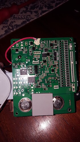
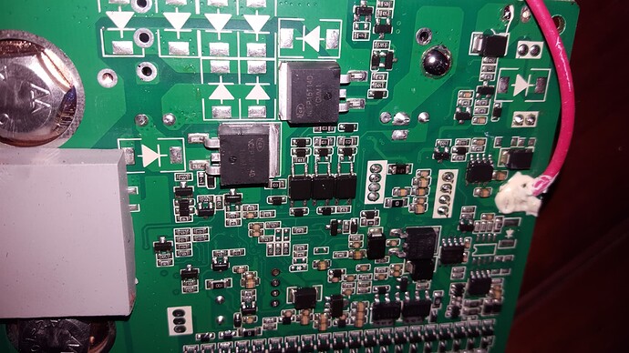
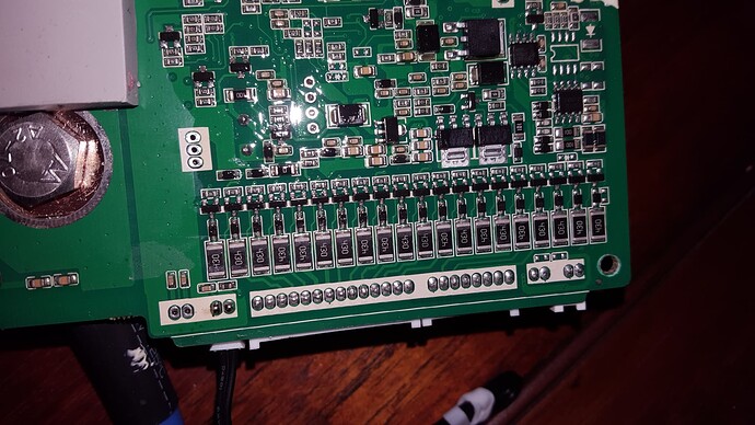
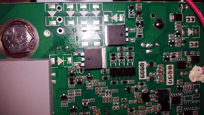
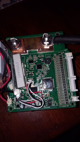
Over the weekend TTT lend me JBD BMS to test it out to see how it works.

Here some photos of the unit for close inspection.


There is 2 FETs on the rear of the board that connects to two resistors, the 10w ceramic one and just under it is a smaller one. From there there is another black wire that runs to the neg side on top of the contactor that supplies the charge/inverter side.

So what I did was, I adjusted in the software app to let the contactor open by adjusting the cell protection to 3.35v because my cells was all above 3.4v standing. Showing on the app that the Charge part is off, the inverter stayed on, so I guess that the black wire that is connected on the bms and contactor supplies some sort of power till the cell settles back under the safety settings and then the contactor closes again.

Some BMSs have ‘pre-charge’ and ‘pre-discharge’ circuits which are made up of FETs (in the same arrangement that the protection FETs are usually in) with a series resistor to limit the current. That’s my guess as to the purpose of those two FETs with the big resistors.

1 Like

I agree. That resistor is way too small to handle any real current. Without any additional current limiting, 50V at 10Ω is 5 amps and a potential 250W dissipation. I agree with you that that resistor is most likely for precharging.

You need to do two things here. Measure the voltage before the contactor (so you get the actual series voltage of the cells inside the battery), then compare that with the voltage on the inverter side. Usually the inverter side will be slightly higher (because it’s slowly charging).

Now do something so that the battery slowly discharges. If the battery has directional charge control, the voltage will drop until it reaches the internal battery voltage, and then hold as the battery starts to supply charge through the directional discharge path (which is still closed, in theory).

If there is no directional control, the voltage will drop out completely and the inverter will switch off.

Edit: Oh, btw, you need to do this without solar power connected to the DC bus. Otherwise you may just be running from the solar power and the capacitors on the DC bus…