If one does this, I presume be aware to drop the charge current If you are like charging with 2 x 5kva’s?
Unless the BMS left, can handle it?
If one does this, I presume be aware to drop the charge current If you are like charging with 2 x 5kva’s?
Unless the BMS left, can handle it?
I’m not n big fan of Chargery bms. There is some stories on the net to. The problem that I founded is that contactor control. If that thing opens, then you have white magic when your mppts is up and running. Yes, if you have software or a setup that can control that and speak between your inverter and mppt, then you sorted.
This is where Solar MD and Bluenova and Freedom have done there homework and got it work with the contactor setup and have the software to back it up and tested on deffirent brand inverters.
More then 90% of the other brands that we get is running FITs setup. They work. I have seen on my setup. If you have control over your bms and you can adjust the settings, then it helps allot. I’m not going to explain it again because the pro’s on this forum have explain it numerous times about FITs.
The charge/discharge setting limits will be individualized per BMS.
But, I think @Louisvdw script does some fancy footwork at the Victron end as well.
Me neither, but the fancy BMS’s are very expensive.
I like the BMS that @TheTerribleTriplet is using; it interfaces with Victron and can/will? be able to deal with multiple banks using a relay.
The downside is it doesn’t discriminate between switching off charging and switching off load.
Although two BMS’s per bank would achieve that and double the balancing capability to boot.
( And I think they would still be way cheaper).
Personally, I like these BMS’es a LOT!!!
If you can get me, die ongeluksvoeel, to make the above work, I would like that a lot!
Especially if you would do same when you get your cells one day …
Are you game?
I could get it to work probably several ways, but I’ll have to think about the simplest way.
Me and TTT wil do a test on Saterday with one of my banks with the smart Ant bms to see if we can get it connected with rs485/UART that he imports with the contactor bms.
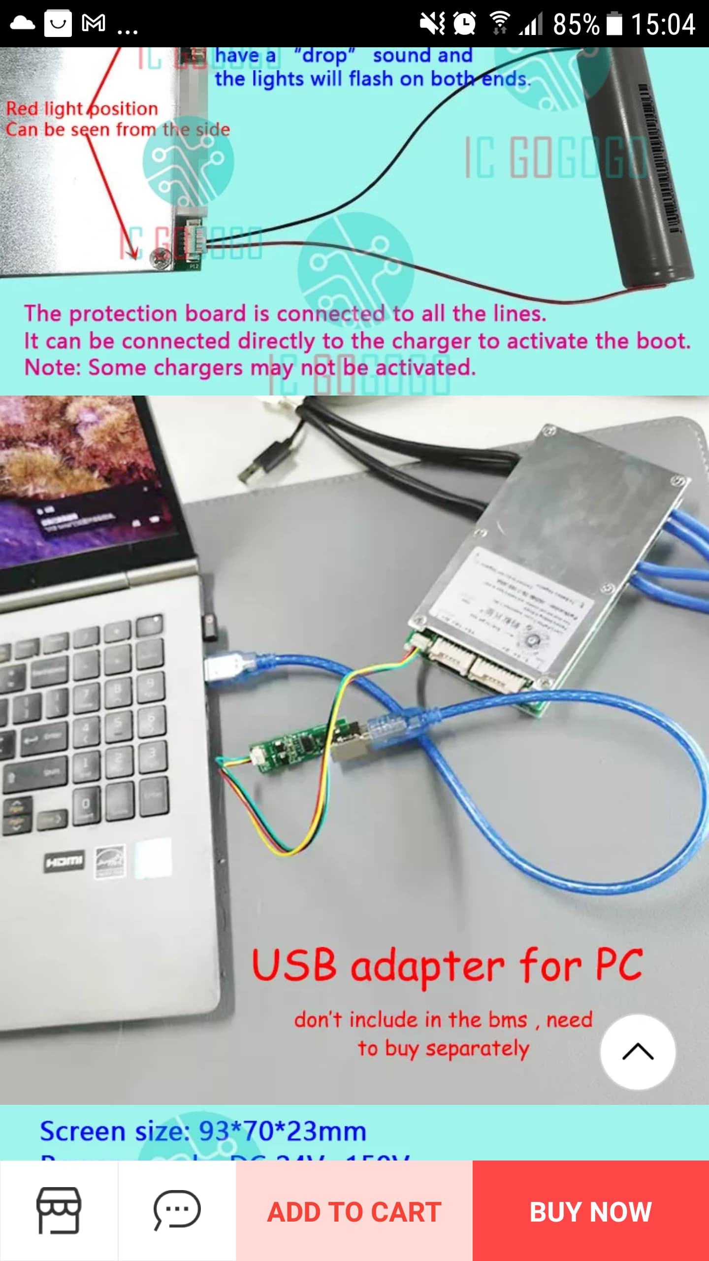
You can get the smart Ant bms with usb to pc connection now. Just to get one now to test it on the bms I got but thr imports via courier is insane.
Remeber Gman, the next cells are being ordered soon … we can bring in BMS’s in the same pallet, for cents on the dollar.
Even got Amy to get the BMS’e we want for us to where they ship the cells from … pay her to get them for us.
@Phil.g00 , tell you what, I will order this model again … Jiabaida Bms 7-20s 200a Smart Bms For Litnium Ion Battery Pack Wireless And Forced Equalizztion - Buy Smart Bms,Bms 16s 200a,Bms For Lithium Ion Battery Pack Product on Alibaba.com
Like it for the nice box …
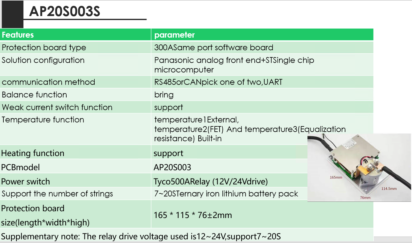
They also have this one out now … AP20S003S - bigger relay AND 24v/48v too.
Looks good, my prefered choice so far.
Which one … AP20S003 or AP20S003S?
With a case and “smaller” relay or without a case and “bigger” relay?
The case is “safer” in my thoughts.
There seems to be a good reason for this. I have been looking at a few BMSs recently to see how / why they have done certain things and after checking the model and no. of FETs on some of the 100A FET based BMSs, I realised that they can’t do more than 100A for any length of time just because of the energy the FETs would have to dissipate. Most of these FET based BMSs have little to no heatsink on the FETs and they all use passive cooling. Since the losses go up with the square of the current, it makes it difficult to handle much more current without massively increasing the number of FETs and / or adding a decent heatsink with a fan. My quick calculation for one of the 100A BMSs I have gives about 10.5W conduction losses in the FETs at 100A. At 200A that would be 42W. I know from experience that 40W will make even a fairly big heatsink get very toasty if you don’t add a fan. So I think it probably ends up being cheaper to just use a big relay that can handle the current.
Remember that my driver can do ANT bms now as well (but I can’t remember if you use a Victron system). You connect to the ANT through the screen port using a RS485 connector.
I spotted that post. That is super great news that ![]() I’m going to run a mixed system. MLT inverters and the other part of the system Victron. Ek stuur jou gou a pm.
I’m going to run a mixed system. MLT inverters and the other part of the system Victron. Ek stuur jou gou a pm.
I do have to question if all this worry about seperate charge/discharge connections is worth the hype?
The way I see it by the time your BMS stops charging by opening the relay/FET then something has already gone wrong. That is the reason that the BMS is protecting the battery. You don’t want to get to that stage.
Either your charger’s settings is wrong as it should have stopped pushing more charge, or it is not connected to a management system and does not know the state of the battery. (think old dumb Daly BMS here).
Or you are drawing your batteries too low. And they you don’t have power anyway.
My fav is 10.1.1.x - uncommon but very fast to type.
I can show you the picture on the GX device:
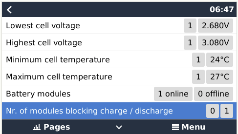
You see that line counting modules that are online and offline? That is what happens, the module (aka bank, string, whatever) that has the problem disconnects, and the rest of the battery continues without it.
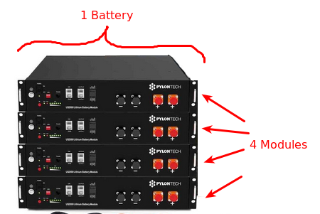
You see this quite clearly with Pylontech batteries where one of the modules have a high cell. That module disconnects, the battery continues without it, as soon as the high cell dies down a bit, the module reconnects, and so it continues. It gives you stability. It is also why I tell people to rather use two smaller modules instead of one large one.
What happens with Pylontech (and others), is each module (bank, string, whatever) has its own BMS, but they all speak to one master BMU (that is what BYD calls it), and this master then presents the unified stack as a single “battery” to the inverter.
If you want the same capability, to have only the problematic “bank” disconnect, you will need a BMS for each one, and then you will have a relay/contactor for each “bank”. That is of course costly.
It is really really nice, but I don’t think it is essential. The popular Pylontech battery doesn’t have it (or at least didn’t have it in the US2000, and I don’t know that they got it in the mean time). It works just fine, but what they do have is a BMS per module and individual control, which adds a lot of stability on that end.
Of course the fact that the big brand names have a disconnect per module, means it doesn’t have to be that big, and that allows them to get away with a bank of FETs (on each one). When talking a single BMS for the entire 200A thing… Stanley is spot on. It is probably not going to happen.
I suppose this is a “cake and eat it” situation. You can have it cheap, good, and with directional control. Pick two.
Or to really drive it down…
What @Stanley said, thank you! Pennie dropped for me as it is exactly the same as what Jiabaida alluded to … if one could “get” the Chinese Ingelish. On top of that, electronic equipment operating under “stress”, being 280ah single “modules”, and we know people are going to have more than one “module”, it is best not to stress test a BMS. 
@Louisvdw, adding to what you say, which is the reason why I keep coming back to what are the “best safe long life” settings to use, is that this “drive” to get the charge/discharge split is based on WHEN the cells go out of whack and one misses it, the BMS then disconnects to protect the bank … that infamous DC Ripple will enter the equation. On a balanced bank, it will not happen no.
Maybe add a warning in the driver to prominently give a visual warning and a beep, when a severe imbalance happens between Lowest/Highest cell?
As far as I know, I’m one of 2 people that has had this problem, me the only one “shouting” about it, the other guy lost a 250/100. I’m convinced it will happen to someone else too.
As an added precaution, I’m keeping my Smartshunt in the mix, like when BMV said 35% SOC and BMS says 95% SOC. So for me personally, it is just an added “warning”.
@plonkster thank you, makes even more sens now. But you know me … IF I understood @Phil.g00 corrently, if he can get his idea TTT proof i.e. using 2 x BMS’s per bank, then we can have our “cake and eat it” situation. 
Remember guys, when the cells go out of whack … boy, you don’t see it coming … it creeps up on you cause your system is working, stable, so you do a lot less checks … the wham it hits you when you least expect it. I’ve got that T-Shirt, trust me.
Thinking of what @plonkster and @Gman have mentioned over time of what is inside brand names, I “get” why they use smaller ah cells, and only 15.
We here are going for THE biggest cells today AND going 18 cells too, wot, that is 3.45v x 18 = 62.1v x 280ah = 17.39kWh single bank for wot, <R60k? (if you buy group buys)
… vs …
… adding module after module of brand names to get to the same kWh … , that gets very expensive very fast.
When we get this right, settings and BMS’s, and we can get to what Will has mentioned i.e. the cells outlast us, now THAT would be a nice goal to work towards.