So how about you use that spotty consistency and give your thoughts on specs to program the BMS’es at, what voltages to set on the inverters and all that? 
Just because you derailed ANOTHER thread! 
So how about you use that spotty consistency and give your thoughts on specs to program the BMS’es at, what voltages to set on the inverters and all that?
Just because you derailed ANOTHER thread!
The voltages you provided seems fine to me.
I have no clue what cell voltage corresponds with what SOC, in fact I would probably say you shouldn’t bother with such “drift points” between 35% and 85% SoC, and rely on shunt data only in that area. Assuming the BMS allows for it.
I tend to take a way more “loose” attitude towards this. SOC is an estimate. Voltages help at the edges, but not where most of us care about them (around 50%). So it is pointless to endlessly optimise it…
I can SO agree with that lately.
All I’m trying to get to, is what would be the optimal settings for a daily cycled bank?
Not one of the brand names have the same settings … cause the cells differ, and the amount of cells.
And everyone has “their” settings … but none of the banks are 10 years old.
So the question comes about, what are the “right” settings?
Ps. SOC, uhm, is it not quite important on a Victron system using ESS?
You will be amazed just how similar they are (at least those that use LFP cells). The voltages you listed is pretty much bang on what everyone users. Full around 3.5V. Overvoltage at 3.65V. Some will give you a bit more leeway, they will allow you to go to 3.75V. Empty at 2.8V. That’s the recipe, and almost all of them do it that way. Hence me saying… no point in endlessly optimising things.
If however you decide to veer off that beaten path, you want to balance lower down (requiring an active balancer, probably), you want to run with 18 cells and a lower per cell voltage, etc etc… well… then things get more interesting. Because now you are not following the normal “top balanced” recipe that everyone else is doing.
And THERE those absolute gems in teeny bits of info, the small print … for as I read the bold parts, the penny dropped … off course we are veering off the beaten path!
Hence the titibt about an active balancer now becoming a very interesting point to consider.
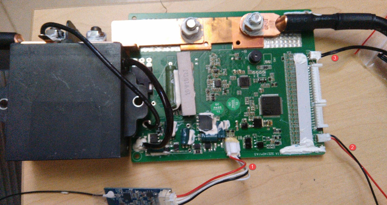
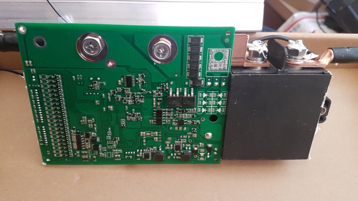
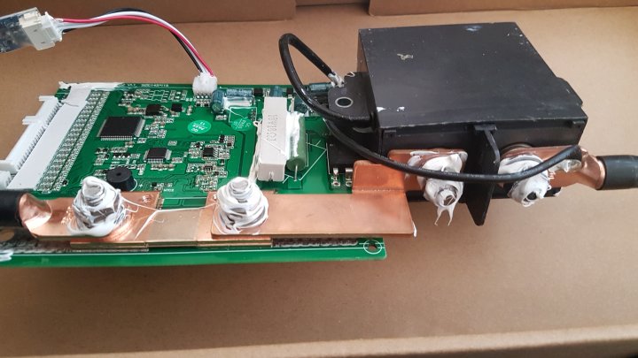
FWIW: the JBD BMS’s do not have FET’s / Relays to split charge/discharge.
And hence, the entire plan changes. With 18 cells, I would probably go to 3.45V per cell (full), that gets you a total battery voltage around 62V. Empty is still at 2.8V.
Since you’re using a fairly low per-cell voltage, there’s going to be less “jumping out” of high cells, and whatever differences there are will be smaller. Smaller differences mean less for a passive balancer to work with, so ideally you would look at an active balancer.
Now you must also keep in mind that while charging or discharging, getting a good consistent voltage “snapshot” is hard. Typically the voltage measurements are a few milliseconds apart, so a battery that is actively charging or discharging may get a voltage reading from a cell, but by the time it decides to do something with it, that reading might be stale. So an active balancer typically works only when the battery is idle (or close to idle), or if there is a clear high cell, and since you spend all your time at lower voltages, it’s going to take forever to balance. Or in other words, a cell with lower charge which just happens to be at more or less the same voltage, will not be pulled up as fast as when you push them into spiking upwards (as you do with top-balancing).
But you may not care about that, since the objective is to keep the battery somewhere in the middle permanently, in other words, even if some cells are left at a slightly lower charge level, you take this compromise because you favour longevity.
But this is the stuff you like to play with. And then you post us long reports with many little “titbits” in them… ![]()
Edit: You could also pull them up to 3.55V once, top-balance them, and then run the battery lower from there on. IE start with it well-balanced. I don’t know, from what I’ve heard it works well if you use well-matched cells.
This is not true. You current 200A model use a relay. They are not all like that. All those up to 100A use FETs
@Louisvdw , I REALLY hope it is true … but this is what Jiabaida came back with this afternoon:
When charging is off, the relay is off, and it can’t be discharged.
Our BMS is same port for charge and discharge.
How would I check it … without blowing shiite up?
It would need two relays, and two relays would need a minimum of 3 main current terminals to break charge and discharge current paths.
That’s only two, an “in” and an “out” and only a single relay.
Some further light reading about the bi-directional Chargery solution:
Am aware of them yes … till @Gman told me to watch this …

If you want to discriminate using your particular BMS, you will need two of them per battery bank with a relay in the charge line and a relay in the discharge line.
Then you will have to use the settings intelligently to discriminate when you want to switch each relay.
Honestly, I rather get another model BMS that has the functionality built in … that can interface with Victron via Louis driver AND that has a Bluetooth App.
Louis suggested the JK BMS, I’m looking at them … any other suggestions that are on Alibaba, would be much appreciated, as we need a few right now.
Chargery is the only one I know of, that has a 300A+ current-carrying capacity relay and discriminates between charging and discharging.
You want at least 1C capability on those 280Ah cells.
I think some of the current ratings of those FET models are “ambitious”.
Question: And on a 5kva inverter, with a 250/100 MPPT?
I recon if one has more than one battery bank, that one would need a BMS per bank, correct?
In your instance, you’d get away with it.
It depends on how you configure your batteries’ busbars. If they are discrete banks and you want to switch them in/out as discrete banks, then yes.
Could you explain this a bit more please?
All banks end up connected to a inverter/s?
So I have say 32 cells:
I could make two banks of 16 cells in series and the parallel the banks. I could use two BMS’s and monitor every cell voltage individually. I could also switch out one bank and leave the other in service.
Or
I could parallel my cells making 16 parallel pairs and then put all the pairs in series. I could use a single BMS to monitor the voltage of each battery pair, but I would have to switch out the entire bank.