Hi guys.
How do I wire up a second MPPT in parallel to the existing one?
I assume that the cabling coming out of the 2nd MPPT must now go to the 1st MPPT and not also to the inverter?
Do I actually connect the 2 units like you would batteries in parallel?
So the 1st MPPT would have in its battery (+) terminal two cables. One coming from the 2nd unit’s battery (+) and one going out to the inverter? And the same with the (-) cable?
Please help with advice or a diagram or something. 
Why do you want to parallel them?
Connect panels to each MPPT, connect both MPPT’s to same spot on the batteries.
EDIT 1: Make sure their settings are identical.
EDIT 2: Connect both to your Venus.
Unless you have the CANbus range of MPPT’s … for moerse large arrays.
Both MPPTs go to the batteries, or to your battery bus.
See here in these picture below.
In the centre bottom you will see that I have a negative and positive bus. Of the 3 cables for each, the left most set (+ and -) go to the battery. The centre set (+ and -) go to the one MPPT and the right most set (+ and -) got the the other MPPT.
If your current MPPT connect to the battery terminals of the Inverter, then both can connect there. I find that things get a bit tight, so mine goes to the battery (actually to the fused port(s) of the battery) and the battery has it’s own big thick cable to the inverter.
It sounds to me like in your install, you have the MPPTs battery terminals wired to the DC terminals on the inverter.
This is a valid way of doing it, but not one I’m particularly fond of. I pref to have a busbar somewhere, and for everything to “star” off from there.
But to answer your question at least partly, I would not wire MPPT1 to MPPT2. I’d wire both MPPTs to a common connection point (eg a busbar) and then wire that point to the batteries.
Thank you all, ok so its that simple. Seems I stared myself blind at the phrase “wired in parallel”
Correct Plonkster, the MPPT goes straight to the invert’s dc terminals. But as was pointed out, things starts to get a bit tight around there so I think I will add a busbar to the mix where both MPPT’s can join up.
So I then require one more RS485 cable for the 2nd MPPT to communicate with the GX and that’s it.
Cool beans
So this is possible? But not recommended?
If by possible you mean you can get the wire in there, yes perhaps depending on the thickness of your wire.
But the Victron MPPTs terminals are mostly designed to handle the cable that one MPPT’s current are required for, so you will either be putting in far to small wires if you can make it fit or you are going to make some hack to make it work. Neither is a good idea.
You mean one more VE.Direct cable (it’s actually an isolated USB to TTL-serial converter).
Hi all.
I am in need of assistance again. I finished installing the 2nd MPPT about an hour ago. It is not the greatest of days for solar in Pta today, but I did manage an extra 1Kw from the additional panels.
So time will tell how they perform together.
I checked that both MPPT’s settings are the same.
I did the latest firmware and software update for the 2nd MPPT
No other settings were changed, including the “Keep batteries charged” which is what I’ve been using the past month.
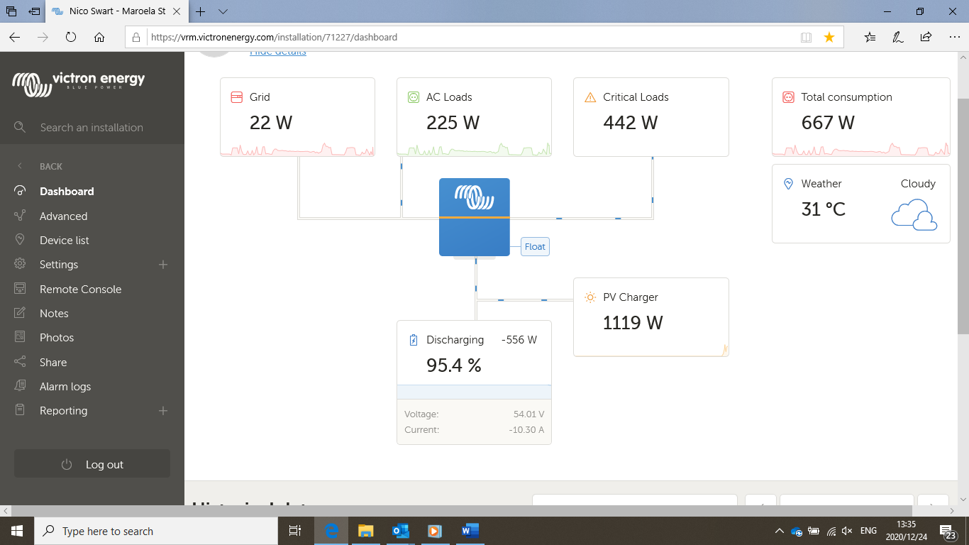
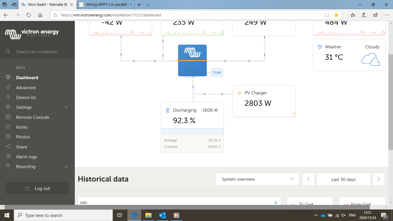
However, now my battery is discharging? Why is this?
Feeding back to grid was on.
MPPT’s charge voltages were set too high compared to the inverter.
I think it is now fixed, just check all the settings again, please!
Rebooted Venus, but it still does not Keep Batteries charged.
Have to prepare for a party … anyone whom can help?
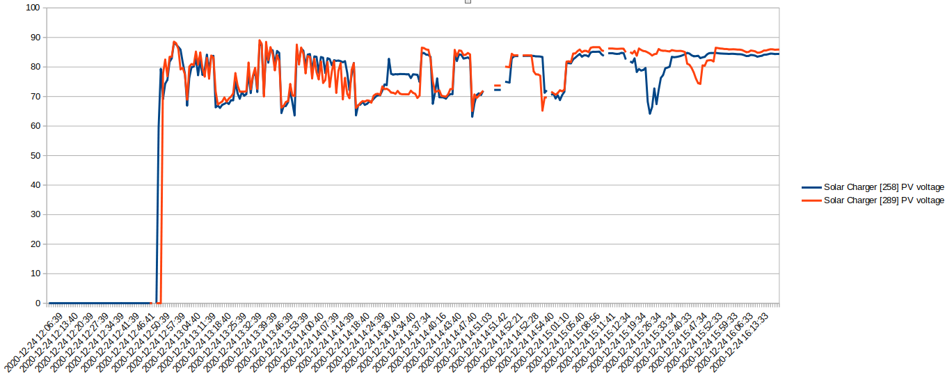
Just looking at your data but something does not seem right.
I suspect you have (had) your PV inputs in parallel.
Before 3PM the two solar chargers report similar PV voltages all the time, which is unlikely. You can also see them fighting each other.
The PV inputs should not be in parallel. Only the battery side (which happens implicitly since they connect to the battery in the same spot as the other one).
Hi Plonkster.
Not sure how I did this. Maybe you can confirm if this is so. This is what I did.
The 1st MPPT is connected directly to the battery terminals of the inverter.
The 2nd MPPT’s cables I connected to the battery terminals due to space constraints at the inverter terminals.
Only thing I did different this time, is that both MPPT’s + cables goes through dc breakers.
So have to confess, no idea if I paralleled them or not. And then if I have, how do I fix it?
Should they both be connected at exactly the same terminals? Be this battery or inverter’s battery terminals?
The PV cables (marked as PV on the MPPT) should have no interconnection between the strings. One string is connected to the one MPPT, another string is connected to the other.
Internally the MPPTs already connect the negative of the PV side to the negative of the battery, so the negative ends up being commoned anyway. I have seen at least one install in the past where someone accidentally had the positives bridged (nogal at the breaker) and ended up with the two MPPTs fighting each other.
I am merely guessing based on past experience. If the PV voltages are the same all the time, it usually means something got messed up somewhere. After 3PM on that chartm the voltages seem disconnected from each other, almost as if something was fixed. Again… I’m just guessing.
I almost got excited here when you said bridging positives at the breaker.
I did do something like that, but not quite like that.
Both MPPT’s has 3 strings each, consisting of 2 panels in serie.
So each string for both MPPT’s has its own positive cable going into a breaker.
So 3 breakers for each MPPT. So 3 positive wires enter their respective breakers, and on the other side those breakers are bridged so that only one positive wire goes to the MPPT.
Same with the other MPPT. On the roof, both MPPT’s negative wires are joined so that only 2 black wires come to the MPPT.
So I’m fairly sure I didn’t bridge the positive wires from the different MPPT strings.
Only bridging that was done was between the 3 strings of each MPPT.
So 12 modules in total. 6 Modules on each MPPT, and arranged in a 2-series 3-parallel arrangement?
Then the fact that the PV voltages seemed to follow was a coincidence. Then I’m afraid I do not know what is up. Will have to spend more time studying the data if you have not yet figured it out yourself?
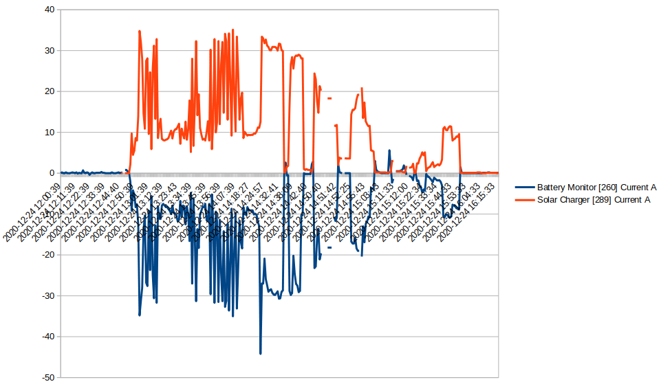
Hang on just a tad… the power does not add up correctly. Your BMV shows current coming out of the battery, but if you add the PV plus what comes out of the battery it does not correspond with what is going to loads or into the grid.
I have a theory…
<insert 3 minute space in here as I study the data>
Bingo!
You’ve got the second MPPT connected on the wrong side of the BMV’s shunt. Note in the chart how the battery current mirrors the solar charger current. Positive current for the MPPT shows up as negative on the BMV.
1 Like
Plonkster, I would have never have thought of that. You are correct. The 2nd MPPT is directly on the battery. And the 1st MPPT is directly on the inverter. Meaning I have MPPT’s on both sides of the shunt!!!
Jaco de Jongh mentioned the exact same thing today but we didn’t have time to explore it further due me not being home and it being Christmas and everything.
Jis julle ouens is slim!
Thanks a lot!!! Thank you so so much!!!
I’ll only be home Sunday, would the system be ok if I leave it like that for another day like that?
I suppose the biggest harm can come from the battery being drained too far.