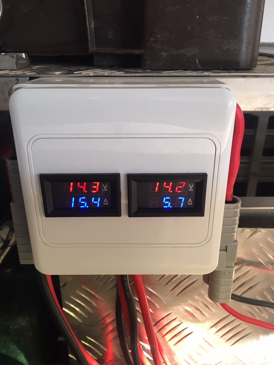
But a couple of years ago they just stopped working and the screens are dead. So I suspect one of the sensing wires or something that gives the screen its power.
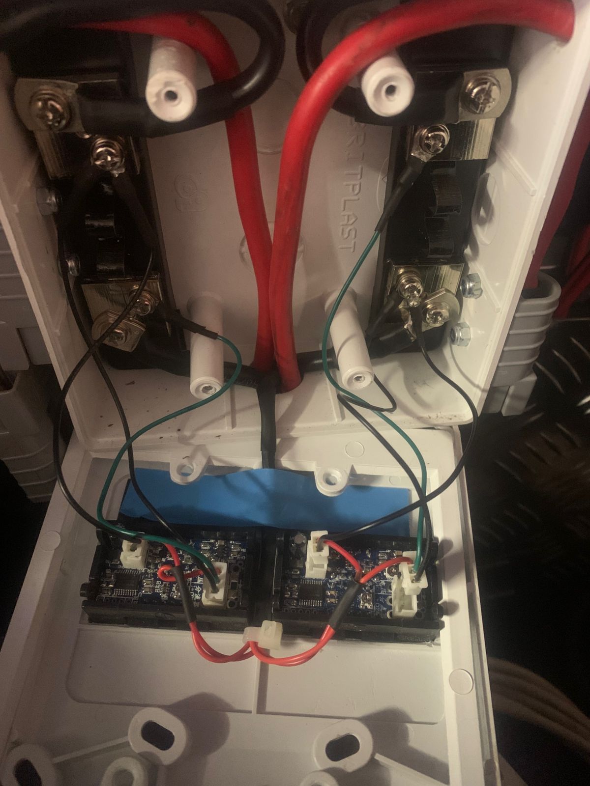
I have removed the 2 meters now, but left the wiring in place in the box that goes to the shunts and the respective load and source wires. It will be a huge thing to take them out.
I don’t just want to replace the meters and then there is an issue somewhere else.
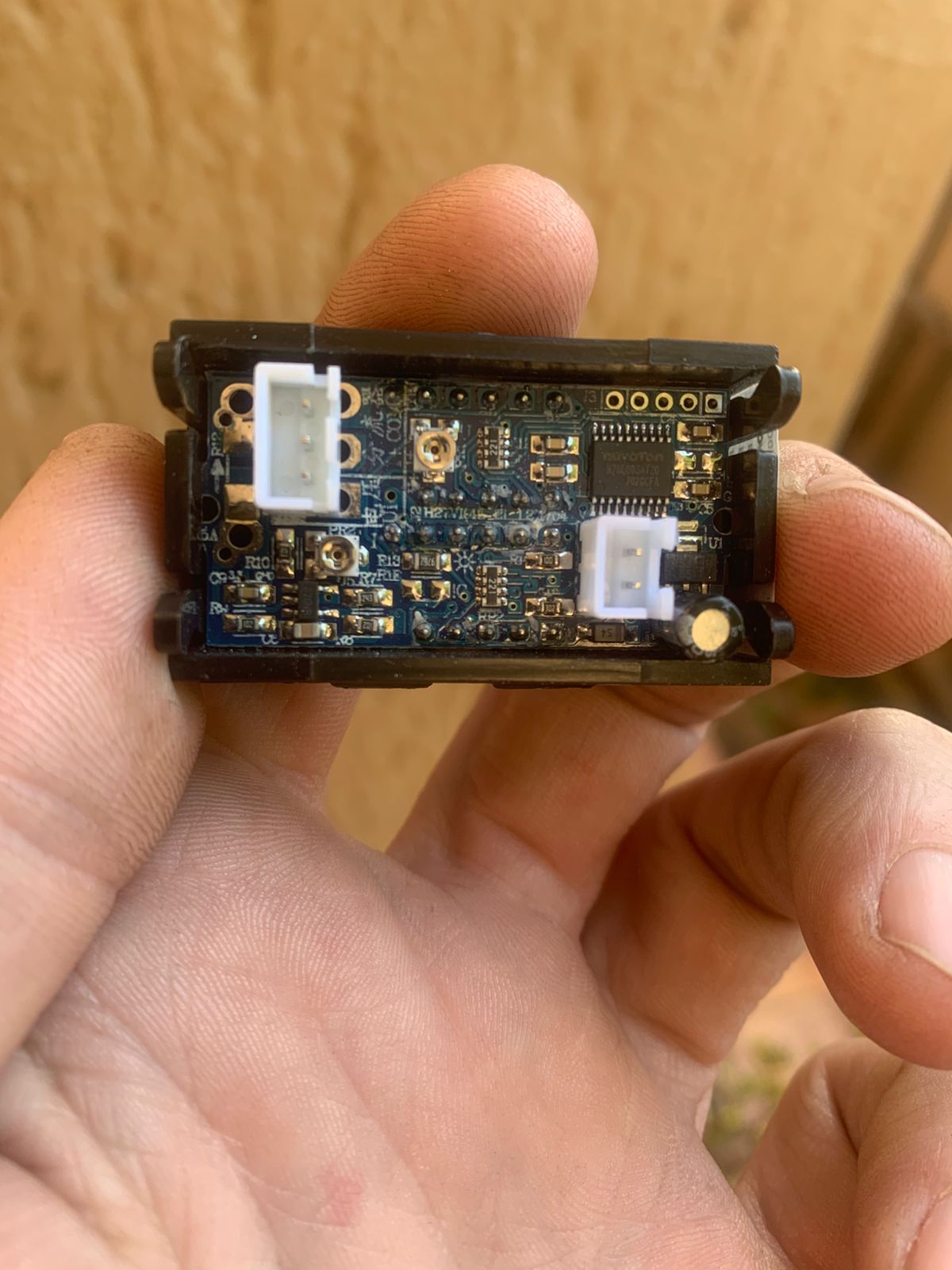
They have 2 sockets on them. A 2 pin and a 3 pin for volts and amps. Cant remember which is which.
At the risk of asking a very stupid question… the sockets seems keyed, and since one has two pins and the other has three pins… it would seem it can only go in one way?
OK… so the question then is not the “I forgot which is which part”, but rather “how do I test them”? Them being the little boards? I’d assume just powering them up, no need to connect the shunt, will do the trick.
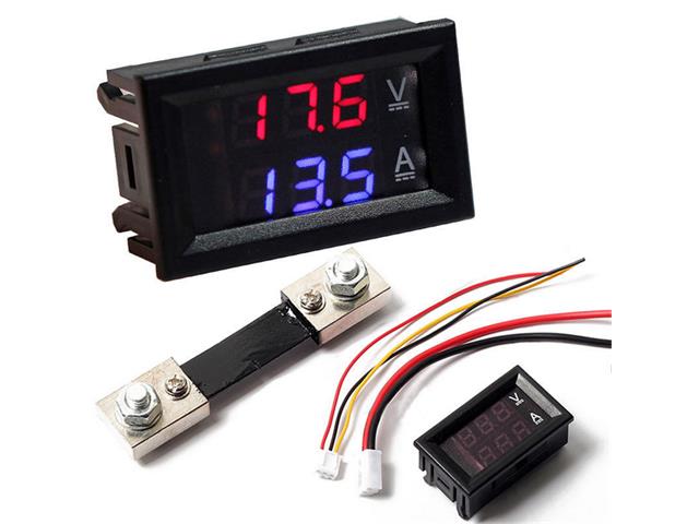
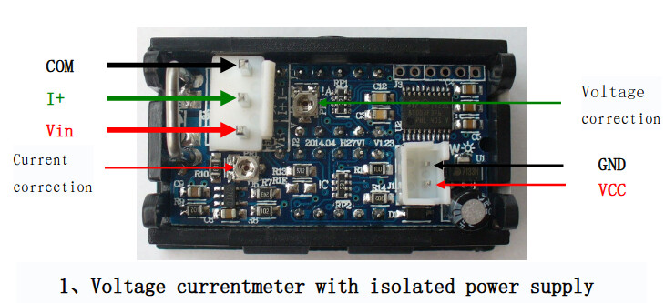
I chucked that into google image search and found this:
Looks like it has a supply that is separate to the measured voltage. You probably just need to put 5V to the two-pin plug, in the right polarity, and check if the display fires up.
Edit: The board pictured here has a soldered in shunt, while with yours the shunt is external.
Thank you Plonkster, julle ouens figure darem goete vinnig uit! Google image search? Ek het nog nie eers daarvan gehoor nie lol.
Dit laat mens wonder hoe de hel 'n idjit soos ek daardie boks kon bedraad destyds, maar ek het dit beslis alles self gedoen. Nou kan ek dit self skaars glo.
Ok, nou moet ek uitfigure hoe om 'n 5V bron te maak.
And here I am under the impression that the 12V in the vehicle battery powers everything up? Why or how does it need/get 5Volt input when it is wired in?
Indeed. While the board has a separate supply, the supply can be anything from 5V to about 28V according to the page I linked (it is under the “found this:”). So you can just power that from 12V.
For myself, I find that a 5V supply is often easier to find. A USB charger is 5V… plugging in an arduino and using the 5V supply from that board would work… and so on. The 5V wire on that USB-ttl thing we use to program ESP8266 aka sonoffs wil work… but you can also just use 12V.
Right click on your picture above, then select “Copy Image” from the context menu. Then go to images.google.com, click here…
If they are both dead, I suspect something went wrong with the VCC supply. I have one lying around somewhere that I don’t have a shunt for, but I probably won’t be able to find it, unless I’m not interested in finding it… That said, they should cost less than shipping would (without the shunt)…
I’ll see if I can find it tonight or over the weekend.
I won’t be surprized if the ones you get from your reputable supplier come from the same factory as the Temu crap in this particular case. For R37 I say take the risk and buy a handful…
I’ve got 2 of these that I got from 4 x 4 Direct many moons ago, the 20A version. Don’t use them anymore so you welcome to them if you don’t come right with _a_a_a. Drop me a line, PUDO locker-locker is only R49.
Went to an electronic shop yesterday and bought the 2 pin plug which had wires already.
Unfortunately they didn’t have the 3 pin with wires so I got the loose plug with internal pins separate and tried to attach some wires myself and insert these.
Man those pins are small. I stuffed up 6 of them (bought a spare set of pins in case of error) and gave up.
The 2 pin unit shows my meters to be as dead as a mossie.