Victron MPII Inverter Overload

Well, not only cables that are too thin, let’s just cover all bases here. It could by anything in the path that creates a higher impedance, for example, a poorly crimped lug could do it.

There are two ways to check your DC ripple, the more proper way (which needs expensive equipment) and the DIY way (which you can do with a multimeter). The “more proper” way is to attach an osciloscope to the terminals of the Multi, and run it at full load. What you will see on the scope is almost what looks like an inverted half-sinewave on top of the DC, with a frequency of about 100Hz. The so-called DC ripple. This is completely normal, but you don’t want this ripple to be too large. At full load this could be as much as a couple hundred millivolt, measured from the bottom to the top. The Multi starts to complain when the ripple exceeds 1V.

The cheap way is to put the multimeter on the AC range and to simply measure the DC terminals on the Multi. Because the meter has AC decoupling capacitors on this range, the DC is filtered out and you see only the AC component. If you have a true RMS meter, you should get the same result as with the scope. If you have a cheaper meter (don’t we all!), you will still get a result (in the sense that a large value is bad news), but it might not correspond precisely to the value you’d measure with better equipment.

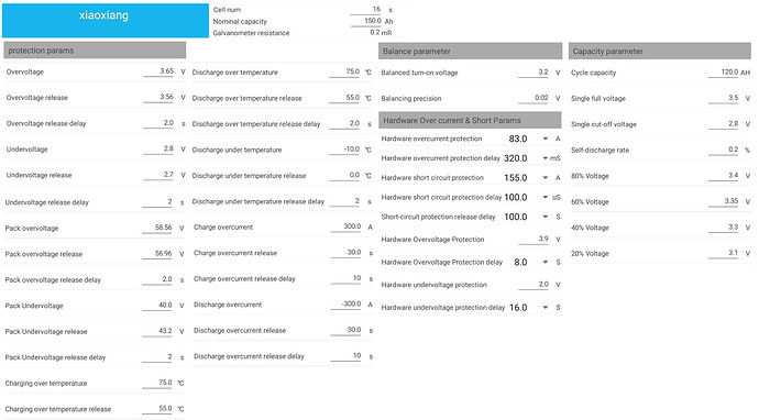
@VisN has a pylontech rack. I don’t think we need to worry about the BMS doing weird things, unlike the Daly the Pylontech BMS is well tested with Victron inverters by both Victron and Pylontech. As I have said repeatedly now, the theories thrown about are all things that manifest clearly and leave traces in the telemetrics (aka VRM), of which none have been seen.

So my suggestion is to get a good True RMS meter and measure with the AC range on the DC cabling while the inverter is under load. If you don’t see a value approaching 1V, DC ripple is not the problem. Ideally you want to see <500mV.

Thanks all. I’ll see what I can do to mitigate DC ripple.

1 Like

@plonkster , hoor my lied …

This is 100% correct, I don’t dispute the tests at all. Must be done.

BUT, here is the thing. I can show you, and Victron, that with:

  1. 70mm2 cable (<5m return) OR 50mm2 (<2m return),
  2. Professionally hydraulically crimped lugs,
  3. BMS interfaces with Venus,
    … that I can create a DC Ripple nearly on demand with a lithium bank.

As I have repeatedly stated to you and a Victron dealer, in my and my clients cases, and now with the 12v setup, it NEVER EVER happens at full load EVER.

Always at >95% SOC (as per BMV) and < 300w AC.

As a matter of fact, this morning, on the 12v system, ZERO load with SOC 100% and ZERO amps going into battery the whole night, the 12v BMS disconnected because of 1 cell.

Cabling and crimps ARE the first port of call, past experiences dictates that, but that point becomes moot when the cabling / crimps are within specs and the problem never ever presents itself at full power, SOC <95%, with loads coming off/on

With lithium banks, this check must be done: Check the MAX cell voltages at time of DC Ripple.

Because you’re running without a battery… practically speaking.

Your situation is not comparable to the one @VisN has, and repeatedly bringing it up makes him stress more! :slight_smile:

Ripple happens for a number of reasons, 1) battery too small for the load, 2) cables too thin, 3) poor crimp or other high impedance in the path, 4) a bad cell in the battery. Your example is case 1 (you’re running with just the electrolytic caps on the bus and the rest disconnected, per definition a very small battery). In this case (if there really is a DC ripple, which I highly doubt) it’s one of the other cases.

My advice remains to test for DC ripple merely to rule it out and quiet the soul… :slight_smile:

Or to put it differently, the size of the cable sometimes has absolutely nothing to do with it. You can make them as thick as you want, but if the BMS at the end of it has disconnected the cells, you’re going to get ripple no matter what you do with the cables. You can get away with thinner and longer cables and still have no ripple at all… just get a proper BMS that doesn’t freak out at 55V… :slight_smile:

I concur 100% … that VIS must also check the max cell volts. :smile:

You mean: 4) a bad cell in the battery. :smile:

As I’m typing this, I’m manually balancing the cells using “The Bulb” on the 100ah 12v lithium bank, 100% SOC, load attached, connected to on Eskom.

As a cell jumps, “The Bulb” gets attached.
3 cells keep on hitting >3.65v, slowly I’m bringing them all in line, target being <3.4v each.

Did same on the main 48v bank, when I got the new BMS, @Louisvdw software helping a LOT to get it done faster.

You’ve got my views, if points 1-3 has been eliminated as a cause for a DC Ripple, as was in ALL my cases, start checking for max cell voltages.

As a matter of fact, with lithiums, check max cell volts first.

Over and Out.

and repeatedly bringing it up makes him stress more! :slight_smile:

:laughing:

I am concerned, no doubt.

1 Like

In this case, the supplier/reseller alleges damage caused by a high DC ripple. My thinking:

  1. Out of the many possible reasons for blowing a row of FETs, how did the supplier figure out so quickly that a DC ripple must be the cause,
    • There was no indication of a ripple warning or alarm on VRM
    • The inverter did not shut down because of a ripple problem, it shut down because of what it thought was an overload.
  2. But let’s humour them and suppose there might be DC ripple, then what would the cause be. It could be:
    • Cables too thin or some other high impedance issue, okay, then let’s test for it using a scope or a good multimeter.
    • It could be that the BMS disconnects the battery, causing the DC bus to spike/ripple/etc. Again, no evidence of this on VRM, and no reason to suspect it given the good track record of Pylontech batteries and the complete lack of overvoltage warnings.

So while I don’t disagree with you that a DC ripple and a disconnecting BMS go together, I’m saying that in this case it is unlikely to be the cause… and that is within the context of very graciously assuming we’re even dealing with a DC ripple, which I really doubt.

In short, there are two scenarios with a high DC ripple. In the first scenario, the battery is disconnected (by the BMS), and the ripple is a symptom of the disconnection. In the second scenario, the battery is NOT disconnected, and the ripple is caused by something else.

This is why your thick cables made absolutely no difference. That’s not where the problem was…

2 Likes

@plonkster, Thank you and the others very very much. It’s very reassuring having a group of guys like you around.


As an aside, does anyone know if there are thicker PylonTech cables available from battery to inverter?

You order a second pair and you use the two open connections on the battery (across from the existing ones) to run a second pair of cables. This doubles up the capacity of the cable.

The stock cables are 25mm^2. On a 3kVA that means they need to handle 60A (ish), and 25mm^2 is ample for that. Honestly, I doubt the thickness of the cable is the issue. If there is an issue at all, it will be because of a poor connection of some sort. Such as a poor crimp, a loose terminal, something like that. But that will show up very quickly if you measure with a good multimeter.

@plonkster, fantastic. Thank you very much.

Guys, the information in here is invaluable.

But having read all this as well as TTT’s issues he had, I don’t want to find myself in a similar position one day when I upgrade to lithiums.

How does one avoid this battery balancing issues? Shouldn’t a proper lithium battery already have the correct balancer tech built in to take care of cell balancing? Why is it necessary to source these units aftermarket?

Or is this only the case when one builds your own bank with 2nd life cells?

If one has the cash, wouldn’t it be better to buy one large capacity battery so there is no cell balancing involved?

Why? And miss all the fun?

Ok, seriously, buy a brand name like Pylontech, Revov etc.

My case, I’m looking and may have found, a BMS that can work across different voltages as well as different cell technologies. For me, THAT is very important … and it comes with school fees.

TTT’s issue was quite simple. He bought a BMS that wasn’t fit for the purpose. The maximum voltage was too low, and as result the protection feature in the BMS activated too soon.

When the BMS activates its protection, it disconnects the battery from the inverter. So now your system is running without a battery, but since there are enough things on the DC bus to keep it going, the system doesn’t necessarily die. Instead, all sorts of other problems show up. Such as a DC ripple.

TTT then did all the usual things, check connections, make sure the cables are thick enough, and so on and so forth. And I am embarrased that he asked me for help and I never even thought of checking the BMS. But in the end all the other things he checked, which he all listed, had nothing to do with his problem.

He got a better BMS, and the problem was solved.

Pretty accurate summary yes.

In contacting the manufacturer of said BMS, the Max volts on, the “translation” from Chinese being correct, all their models are max 60v, and they sell a lot of them locally and internationally.

New information:
Although I bought a new better Multimeter, one would be lucky to find the cell that spikes, at the time it spikes for never once did I measure any cell >3.6v ever. Yet when I did not look …

Furthermore, it was intoned by the local supplier of said BMS that I was the problem, not the BMS, as they had “many other clients using Victron” with the exact same model BMS, that never once reported a problem.

When the new BMS was installed, it beeped like crazy when a cell went out of whack. Seeing all 16 cells simultaneously, o man, it was a jiggle of note to move “The Bulb” between the spiking cells. Reminded me of playing Russian roulette.

When I then replied back to the supplier, once I saw that ±5 cells (if memory serves) were misbehaving at different times … well, lets just say that was a conversation stopper.

The cherry on the cake was Louis software, to further “calm” it all, once I got the worst cells to “relax”. Have not looked back once, the cells are behaving beautifully now, all the time.

So bottom line: Cells misbehaving was the core problem all along, with me and my client.

The BMS didn’t allow you to go high enough. As I recall it would barely allow you to get to 54V? If 15 of your cells are at 3.3V, there isn’t enough room left in the “voltage budget” to get the last one over 3.6V, which is why you never saw one. The BMS disconnected before you could ever see one.

With a proper BMS you see it. Oh boy do you see it. I’ve pushed a BYD battery to over 59V yesterday. It is a well balanced 16-cell battery that allows you to go to 3.75V per cell, so do the math :slight_smile:

AHA … that makes perfect sense.

Correct, could ONLY charge at max 54.50v for 16 cells so 3.4v per cell.
Anything above that and it goes out of whack, nor could I stay on >95% SOC for extended periods either.

New BMS:
Max Operating voltage: 85v, can withstand up to 300v
Max Operating current: 200A
Balancing current: 1st one: 260mA, new one: 160mA
Max Cells: 7 - 20 (24V 36V 48V 60V 72V)

New BMS’s can also go to wot, 3.75v per cell 'cause EVERYTHING is adjustable.

I’m SO chaffed at the moment.

And the 2nd Life cells, 1st bank has now behaved for 36h and counting, not one cell out of whack.
2nd bank … still being assembled … was bottom balanced.

1 Like

@plonkster I’ve decided to take your suggestion to recharge at 2amp.

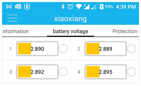
Bottom balancing done, had a minute or so of 20a charging, but all batts started at 2.81v
image

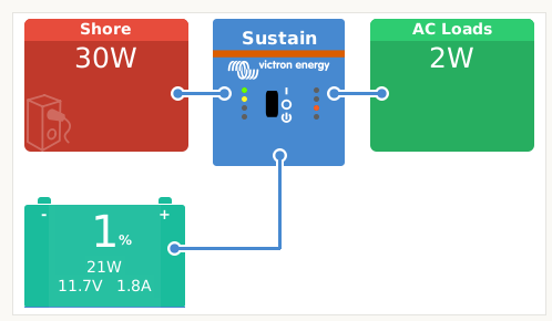
Just the Rpi Venus as a load - 1-3w.
image

Let’s see how this works …

Once done, all 8 cells will make a 12v 200ah bank using 8 cells.

All’s well that ends well. I collected a brand new MP II today.

@plonkster , they are still talking about the cable size. Is there any chance you could show me in a diagram how you suggested connecting the batts to the inverter with a 2nd cable?

Regards