Victron MPII Inverter Overload

There are 4 rows, of 6 each (depending on inverter size). A H-bridge looks like this:

An-H-Bridge-inverter-circuit

Just imagine that for each of the 4 FETs in the picture, you have up to 6 in parallel.

In the older allumium-case models you could even see the heatsink/powerpack arrangement looked a bit like an X, with the 4 legs clearly visible.

If a whole row goes, I wonder if that means one switch, two switches, or all four.

The unit will switch off (and raise a warning and alarm) if there was high DC ripple. Again, you should able to confirm from VRM if there was such a thing.

A DC ripple also doesnā€™t raise the voltage (which is the thing that blows FETs). The peak of the ripple is still at the battery voltage, which with a Pylontech is strictly less than 54V.

I doubt it was DC-ripple. Unless someone can explain to me howā€¦

1 Like

Aaah here is a picture of an older smaller Multiā€¦

I drew two red circles across the top two legs of the H-bridge. The other two is out of sight on the bottom.

The alluminium heatsinks you see in the picture are even individual units (not shared). When you remove the powerpack from this inverter you get a floppy FET and aluminium Christmas tree.

2 Likes

Iā€™ve got some experience with that ā€¦

It has been concluded that my 5kva case AND a blown 250/100 MPPT, that it was BMS related.

Only on a full bank with low AC output to boot, because of cell imbalances getting too high, that caused the Daly BMS to disconnect, resulting in a DC Ripple on the MPII and a damaged 250/100.

Since the new BMS has been installed, me seeing the problem cells volts on my phone, then me helping the BMS with them, and thanks to @Louisvdw software, the problem has been resolved.

And in vaguely related news:
Firmware version 478 just just been released for the MPII random overload and error 11.
It is not published yet but made available on Victron Professional.

1 Like

Are you only updating now??

1 Like

When I looked in Des, it was not there. :wink:

And I only update IF there is a need/additional benefit.
And seeing as I need to switch off all to ā€œclearā€ the Venus, I can just as well do that tonight too.

Yes, but your BMS disconnected, so your case was analogous to running a system without a battery (functionally equivalent to having the MPPT connected directly to the Multi with no battery), and the Multi saw the ripple, complained about it, and logged it to VRM too, didnā€™t it?

Also, donā€™t confuse the symptoms and the cause. When the BMS disconnects the battery a DC ripple and a spike in voltage (Iā€™ve seen as high as 73V) are both symptoms of the event, but it is the high voltage spike that actually blows stuff up.

I did give them access to my VRM.

I could have sworn thatā€™s what I typed :smile: ā€œā€¦ caused the Daly BMS to disconnect, ā€¦.ā€

It did log the warnings yes.
But on occasion where the MPII switched off due to the severity of the DC Ripple, there was a time or two that nothing was logged.

This I think was the case with the 250/100, a high voltage spike.

The core problem, in BOTH my cases, was caused by big cell imbalances with SOC +95%.
Not once on <90% SOC.

Iā€™m not saying anything, just leaving it out there that it can happen on other BMSā€™e as well, that cells are so out of balance that when fully charged, BMS disconnects, as designed.

So I have a Multiplus 12v 500va and 4 x 100ah lithium cells, and a new 12v BMS.

Because of a couple of runaway cells ā€¦ Iā€™m busy sorting them ā€¦

Grid Lost is where the little Multi disconnects from the AC input, smart!

image

THIS is the problem:
image

Next move is to bottom balance at 2.8v ā€¦

That is rather a large imbalance. Unless the BMS is an active BMS, it cannot bottom-balance. Your average passive balancer can only balance at the top, and also only while a small amount of current continues to flow (because it works by bypassing the current flow past the high cell).

So your best bet is to discharge the battery to the point where the cells measure about the same, and then slowly charge it (1A or 2A) until the highest cell is back at 3.75V. What you want to do is 1) have the high cell above the rest, and 2) keep it in this position for as long as possible (hence the slow charge current) so the other cells can catch up.

Lather rinse and repeat. It is painfully slow but it does work.

2 Likes

We have a BYD Premium LV battery in the ā€œtest fleetā€ that had exactly this same imbalance when it was new. I was doing some testing on it this morning, and it has balanced out really nicely.

We still have that one cell spiking to 3.75V, but the other cells are all at 3.55V and above when it gets to this point, which means we can push to a neat 57V before anything starts complaining. This is a battery that freaked out with high voltage alarms at 54.5V when it was newā€¦

1 Like

Bottom Balancing ā€¦ how Iā€™ve got it, been told: Drain the cells to 2.8v.
Got the bank to about 3.15v, split the cells out, connected 2 x car bulbs to each cell, to get to 2.8v.
Once they all are at 2.8v, will connect them in parallel and let them ā€œrestā€ for at least 24h giving the cells time to ā€œequalizeā€ themselves between each other.
Then I will charge them back up - 20amps.

If it does not work, will follow your suggestion too ā€¦

In the meantime:
Have a 2nd 12v bank.
Drained it to where the inverter switched off at Ā±12.48v.
Then started to recharging it back up at 20amps, being the inverters max, to see what happens when it gets full.

If it gives drama, will follow your steps on this bank too.

Want to merge the two banks, just need to figure how to ā€œsplitā€ the 4 x balancing wires over the 8 batteries.

With a passive balancer, the slower the better. The balancer does nothing when the cells are all sitting at the same voltage, and with the flat curve of a lithium the voltages are always close right up to the last minute (>90% SoC). Once your high cell breaks away, this is when you want to slow down the charging, if possible you want to get as close as you can to the capacity of the balancer.

In theory, if you could charge the battery at exactly the amount of current supported by the balancer (often as low as 50mA), the balancer will be able to avoid the high cell from charging at all (by bypassing 100% of the charge current), thereby charging only the low cells.

Of course it is hard to charge that slowly with your average inverter/charger, so the best option is just to go really slowly (2A or so) to give it as much time as possible to get the job done.

But disassembling the battery, putting the cells in parrallel, and then charging them all to 3.5V is probably fasterā€¦ if you have that option.

When I drained the battery, the cells stays in line all the way down too.
Just the bastard runaways at SOC >95%.
BUT, with @Louisvdw software and that other BIG BMS, main system is running like ā€¦ wonder if it is still working? :smile:

Ditto ā€¦ so far, from inverter switching off, then charging at 20amps with SOC currently at 71%, cells are still nicely in line:
image

On this small system, when a cell breaks away, will drop the charge amps to like 1-2 amps, as you suggest.

Have this kit, having horse traded for it, want to use it to run more stuff off-grid evenings as getting more batts for the main system is just not worth it.

So using ESS and Scheduled Charging, will re-charge daytime when the main system has spare, as it is but 350w on this small little thingy.

And when we go camping, this little ā€œsystempieā€ will be simply awesome!

The REASON for me posting all this here is that I have a theory that when one buys a brand name bank, it COULD maybe happen that there is a ā€œrunawayā€ cell one day that causes the BMS to disconnect, resulting in potentially damaging results in maybe some cases.

All from a itch I have to consider getting an inkling to maybe ponder on forming such a though.

What also stumps me, now that I have a BMS that interfaces with the Venus whilst I can access the BMS data/settings at the same time via Bluetooth, why donā€™t all the brand names have this in place already?

Iā€™m glad I held out, that @Louisvdw is on this forum. All because of him. :wink:

It seems to have worked, at 20amps charge, from ā€œflatā€.
Cells are 0.011-0.012v difference with SOC at 100% ā€¦

Settings I did use this time round:

  1. SOC when Bulk finishes: 85%
  2. 100ah bank loaded as 90ah on inverter and BMS
  3. 3.5v charge 3.47v Float
  4. Charge amps set at 20a - the max the little thing can do.

My theory is that with a new bank, drain it to where the inverter switches off, then recharge.
Donā€™t take a ā€œchargedā€ bank and expect it to behave.

The 2nd bank Iā€™m taking to 2.8v, then connect the cells in parallel for 24h, then will see if that also works.

This is further correspondence from the suppliers.


Good afternoon

What is the size and length of your DC cables to the unit? The dc ripple will be caused by using too small cables and or installed too far away from the batteries.

The new unit will fail as well unless fixed.

Regards


The supplied PylonTech inverter cables are 4 AWG (roughly 25 mmĀ²). The Victron MPII manual recommends 35 mmĀ².

@VisN I have a story to share about warranties and Victron and what not.

Iā€™ve had a DC Ripple or two on my 5kva.
Have a client who had the same cells and Daly BMS, within 2 days he also got a DC Ripple or two, last one so bad, his 250/100 blew.
Battery supplier refunded the battery, client got a 1st Life Revov bank.
Victron replaced his MPPT under warranty BUT ā€¦ not again for same error they said.

In both our cases the DC Ripples happened when the SOC was >95% at <300w AC

My cables, 50mm2, where slightly over 5m, shortened them to <2m. No difference.
Clientā€™s sparky did not get the memo, also 50mm2, until that was shortened them to <2m. Also no difference.
And the settings where set as per experts adviceā€™s, which I lowered even more.
In both cases we where told to check crimps and joins. All checked out 100% spot on.

Back to the story.
The truth came out when I got a BMS that can share the data with the Venus and via Bluetooth.
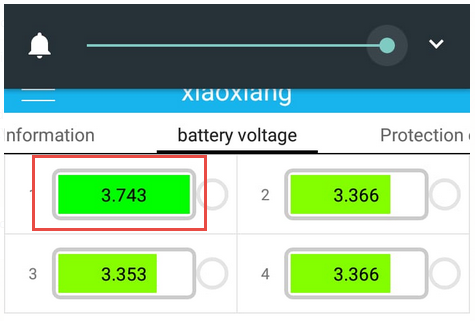
Turns out, in my case, therefor the clients case too having had the same cells and BMS, it was all because of a Daly BMS with cells it could never get balanced, when >95% SOC.

Client got a Revov bank, problem has been gone for months now.
And as I said, I have a new BMS with proper data and interfacing, problem also gone.
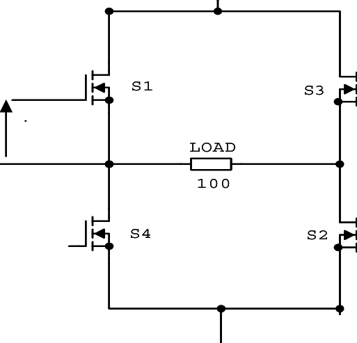
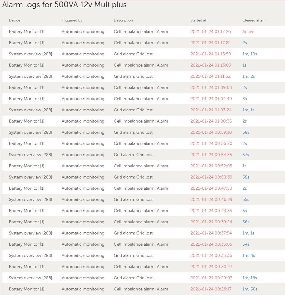
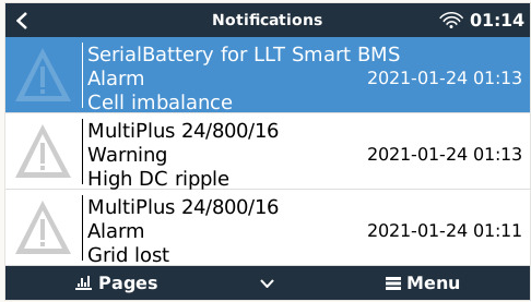
Iā€™m now playing with a 12v system, having a LOT of DC Rippleā€™s, and every single one is because of a cell going too high, BMS disconnecting, affecting the system.

Moral of my story:

  1. If the inverter is not faulty ā€¦
  2. Settings are per manufacturer specs ā€¦
  3. The cabling and connections are spot on and within specs ā€¦

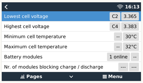
Then the next place to look at are the Min/Max cell voltages in your data.

Because from what Iā€™ve seen so to date, and Iā€™m NOT an expert on lithiumā€™s, is that we must not assume the BMS does itā€™s thing, that the cells stay in line, not even for brand name BMSā€™s.

Well that is most concerning and Iā€™m not sure what the solution is.