There are 4 rows, of 6 each (depending on inverter size). A H-bridge looks like this:
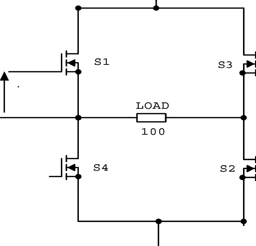
Just imagine that for each of the 4 FETs in the picture, you have up to 6 in parallel.
In the older allumium-case models you could even see the heatsink/powerpack arrangement looked a bit like an X, with the 4 legs clearly visible.
If a whole row goes, I wonder if that means one switch, two switches, or all four.
The unit will switch off (and raise a warning and alarm) if there was high DC ripple. Again, you should able to confirm from VRM if there was such a thing.
A DC ripple also doesn’t raise the voltage (which is the thing that blows FETs). The peak of the ripple is still at the battery voltage, which with a Pylontech is strictly less than 54V.
I doubt it was DC-ripple. Unless someone can explain to me how…