Whilst on this subject is there a convention on the polarity of Universal Solar Connectors?
The same type of connector is used for both positive and negative so all you can do is to reverse one pair to prevent connecting the incorrect polarity…
But is there a convention in which one is ‘reversed’? ![]()
Help me out here.
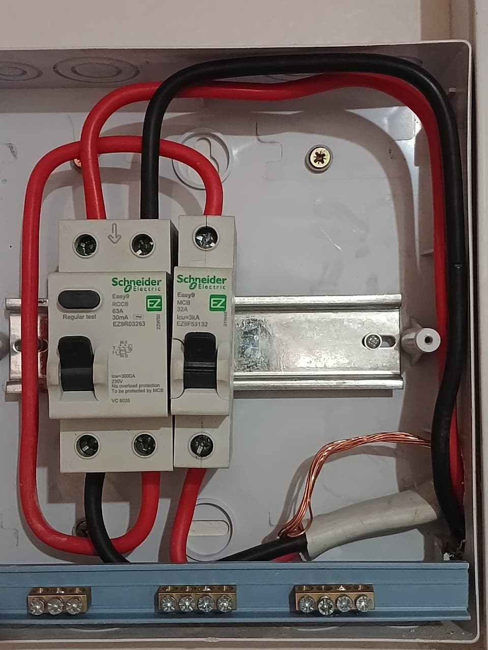
It seems that the main feed going into the breaker and onwards to the RCD was incorrectly connected where it goes out of the RCD and that the earth wire was not even connected?
I also see no neutrals in the busbar below.
I cant really see where the feed goes on or out in the box, but the RCD wiring looks completely wrong. If live goes in on on side, it must exit on the same side.
Aaaaah! I see it!
Polarity swapped on the RCD (in vs out).
Took me long enough…
Only real issue is the swapped input to the RCD. Earth wire is connected directly to the main DB. Only one load, so no real need for neutral or earth bus bars.
But yeah, I would not expect a mistake like that from a qualified electrician…
Right, so following on this thread, I’m not going to hire an electrician for what I want to do.
Well that and the fact that my sparky friend and I are not on speaking terms right now. ![]() We’ll sort our crap out in the new year.
We’ll sort our crap out in the new year.
Thanks Justin, going to save myself some money here. ![]()
But I am kinda stuck so I thought I’d ask some opinions and advice here.
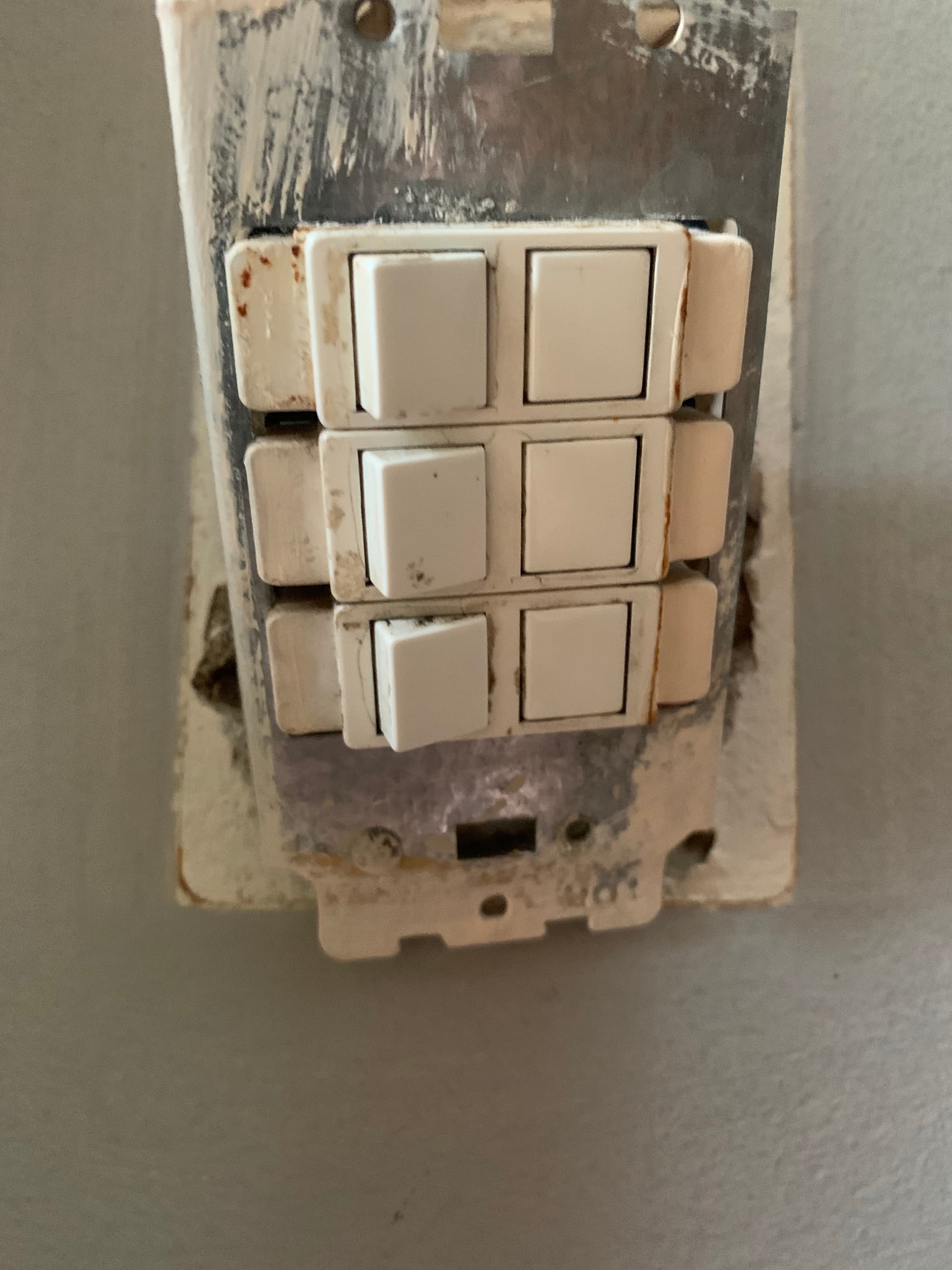
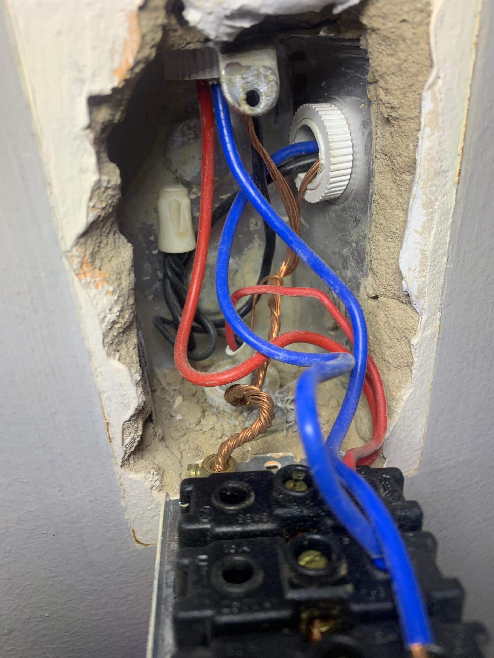
I have this three way light switch at the front door that switches on 3 separate lights ( 2 for outside, and 1 for inside.
I want to replace it with a wifi type and have bought something that seems will be fit for purpose. The manual says it needs a neutral to work and some houses these days apparently doesn’t have these anymore but I’m sure I have it.
Problem is, I cannot figure out the wiring in the house at that particular switch.
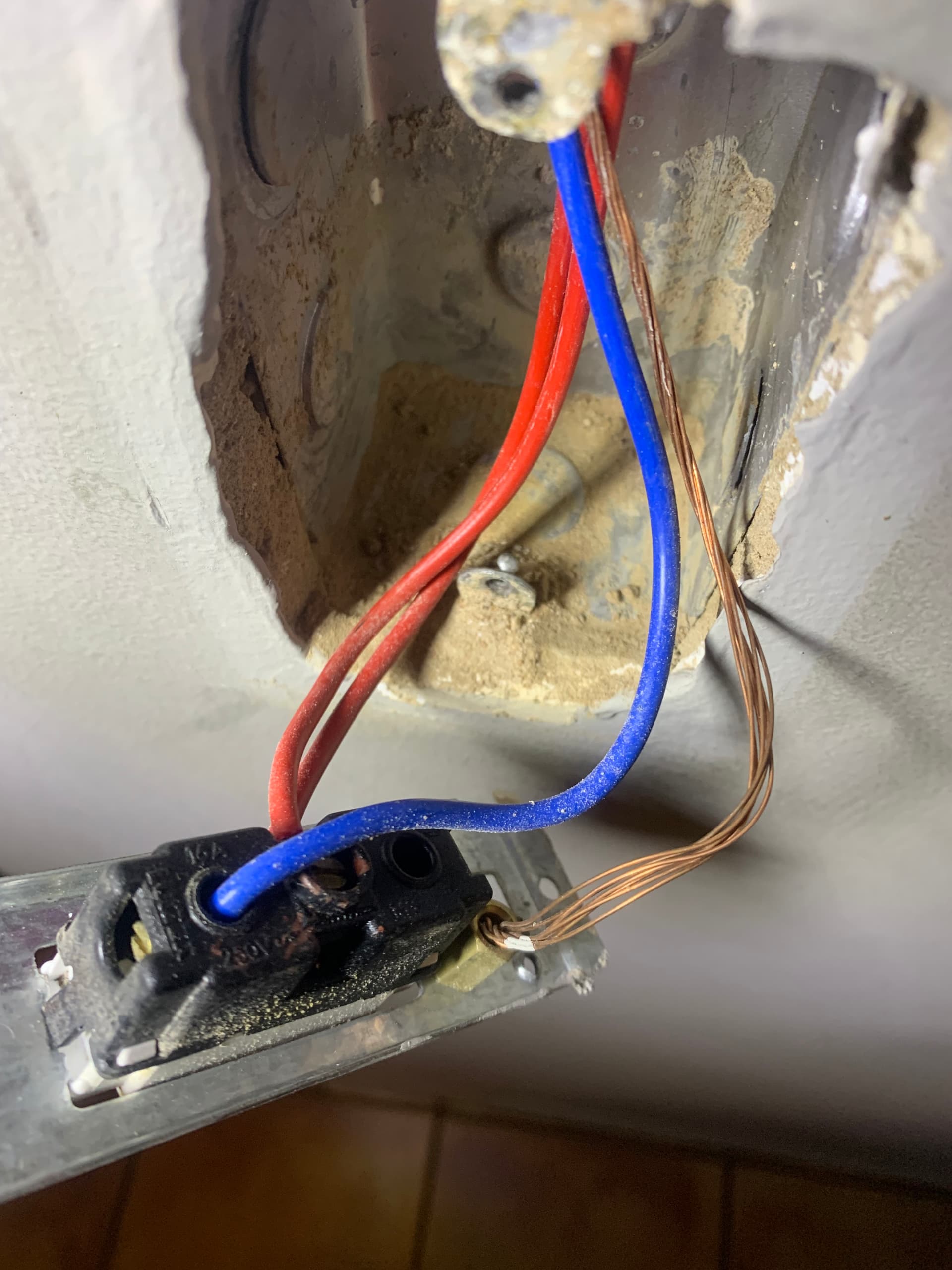
There is one live (red) wire inside it. This goes through all three switches and exits one of them.
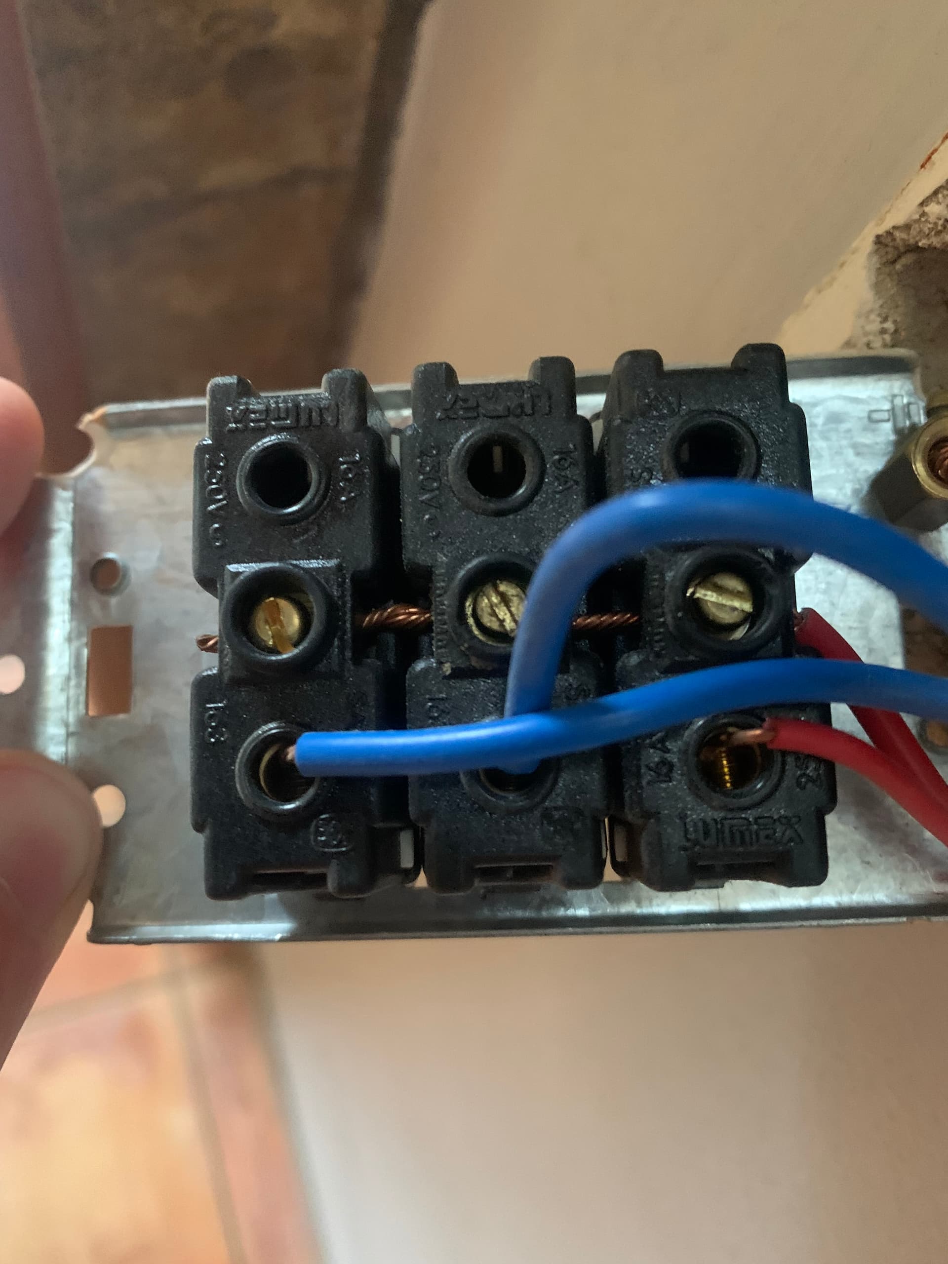
So this I understand. But from the pictures below, there are only 2 neutrals (assuming they’re the blue ones) coming out. So one switch doesn’t have a neutral?
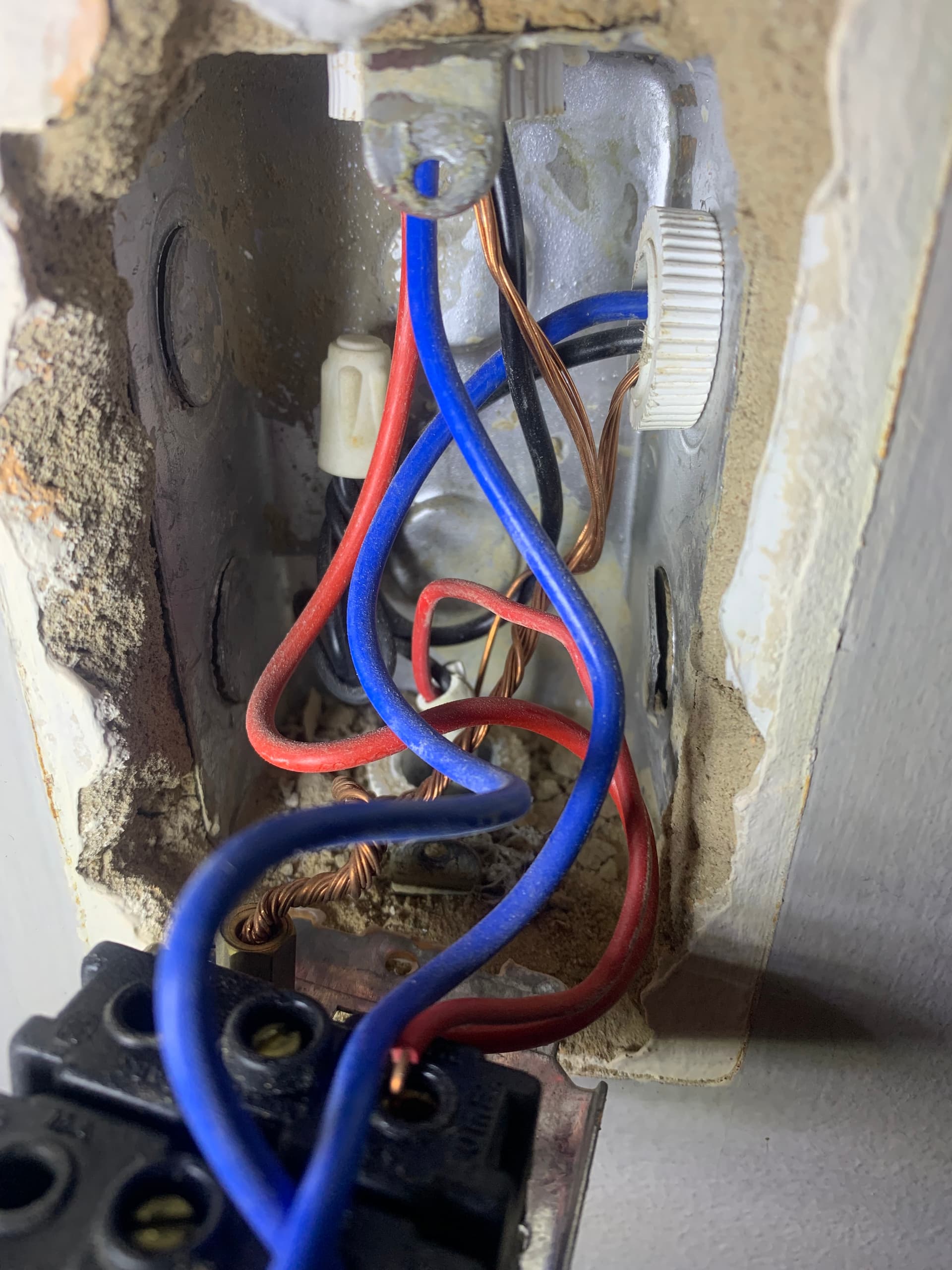
Then, when I look inside the enclosure in the wall, I see 2 black wires just joined together with some sort of proppie thing. What would the black wires be for and why are they joined?
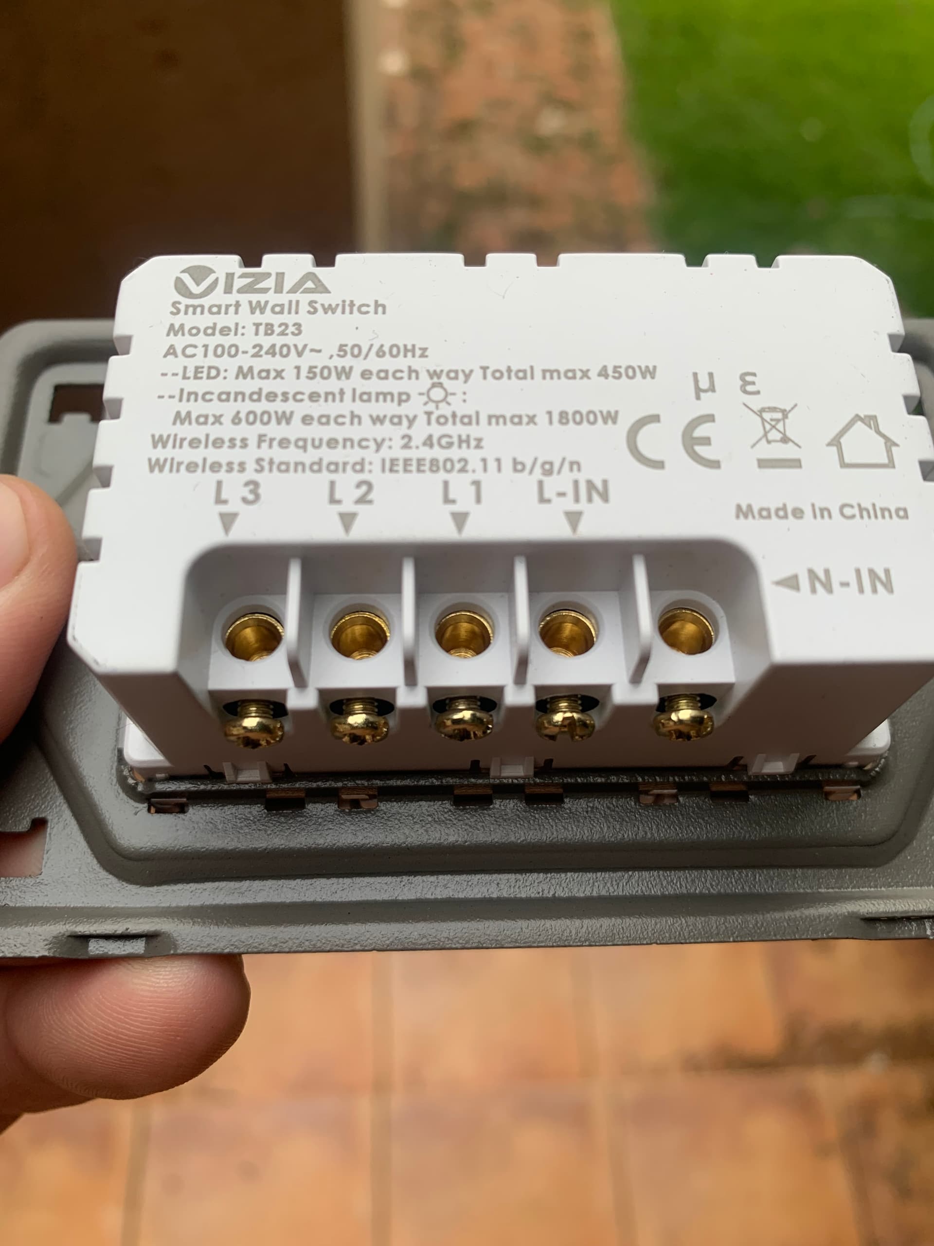
And then comes the part of how to connect these wires to the wifi unit. I can see where the neutral goes in, and the “Live in” wire, and assume that the other sockets marked L1, L2 & L3 is where live goes out again to the actual lights/load.
But there is no place for the earth wire. And would the blue or the black wires now be the neutrals?
My 2 dimensional brain cannot figure this out.

And the pics from inside the wall box.
And here is the replacement unit.
I really would love not to burn my house down, so any thoughts and insight would be much appreciated!
OK… so the blue wires are also live wires, but they are the live wires that goes TO some of your lights lights. The red wire clamped down the middle is the live supply from the distribution board, and the extra red wire leaving is also going to a light.
I’ve seen this convention of using blue wiring for lighting only once (in my previous house) but none of the sparkies who worked there ever asked strange questions about it. I assume it is allowed.
Also… you are lucky…
That is very likely the neutral. It is common to pull the neutral wires to the switch box as well, especially if you are running twin-and-earth or surfix, and then simply join them together in the box.
Is the “proppie” one of these?
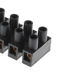
Cause then you can add a short piece of wire from the open end to the neutral terminal of your Wi-Fi switch, and the rest becomes very easy.
Ideally, I would suggest getting a multimeter to make sure about what I just wrote. You need to leave the power on (of course) and not touch anything bare. Then you can check that there is permanent 230V between the red wire going down the middle, and the black wire in the back of the box, and you can check that there is no voltage at the three outgoing terminals when the switch is off, and 230V when the switch is on.
Is it plastic? Then no earth connection to the switch plate is necessary. Put one of those proppies over the earth conductors (just like the neutral) to hold them tightly together, and shove it in the back of the box.
OK I’m an idiot. You posted a photo and I missed it.
OK, that “proppie” is called a wire nut. I don’t think they are even legal to use in SA anymore.
Go to the hardware store and get yourself some of these push-in connectors.
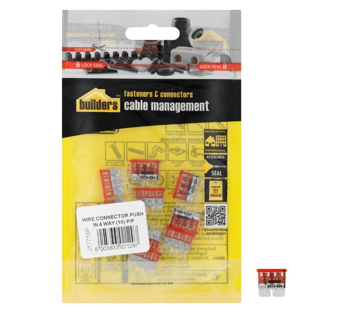
Replace the wire nut with that. Then you can also add a fourth wire that goes to the wifi switch.
I would still suggest clamping the earths together with a terminal block (the clamping sort shown earlier). If you had a crimper I would suggest using a ferule instead.
The Wago 221 connectors are expensive, but once you’ve experienced the joy of working with them it’s hard to go back:
https://www.takealot.com/wago-221-compact-splicing-connectors-5-way-box-of-25/PLID91215610
(ACDC and most other electrical shops also sell them.)
There’s a 5 way, 3 way and a 2 way version. As a bonus they are reusable.
I was about to suggest Wago as well, but because they are usually not available within the half-hour (or however long the trip to the shop takes), these push-in connectors are my second choice. Of course the downside is that any rework on the wires requires cutting them off, so you lose material over time, and in that sense wagos are far better, easier, neater, fast etc.
The blue is kinda what threw me, but what you say makes sense. In my mind, if you start with red, the rest also must be red - my ocd.
You mean they must also go to the switch where the red and blue wires are? Where would they connect?
What I also can’t understand, is how they fulfill their role when they’re just tied together and not going to the actual switch?
So the black wires I just extend so they could go into the neutral connection of the wifi switch? I just wonder how they’re doing their job just tied together in the back of the box.
Have multimeter and will check for this. At least this is something I know how to do.
Yes its plastic. Cool beans.
Ok and then the one red wire leaving the switch and the 2 blue ones are the ones that will go to L1-3 then?
Plonkster!! Your advice was solid man, you rock!!!
I really really appreciate the knowledge you share and that goes for all of you on this forum!!! Thank you so so much!
I am now one step closer to automating my home and my outside lights now work on voice command! ![]()
Have a great weekend everyone!
They are simply permenantly connected. The live side is switched. The neutral wires are simply tied together, or more specifically, the supply is simply tied directly to the load.
In older houses, or when wiring with GP-wire (general purpose, where the two wires are not tied together as with twin-and-earth or surfix), it is common to take the neutral directly from the DB to the light, and not take a detour through the switchbox. That makes it hard to wire Wi-Fi switches that needs a neutral.
In your case, from the photos, it seems the shortest path to some of the lights was simply via that switchbox, and as a result, the neutrals go the same route.
My problem. Found that out the hard way and so now have my Wifi switch in a separate box ![]()
Hi guys,
Looking for some assistance again please.
I bought some more wifi light switches that works on the same Smart Life app. All single switches this time.
Where my previous two switches were 3 ways and had neutral (black) wires in the switch boxes, the couple of single light switches I now want to replace seemingly does not have neutral wires.
These new units came with capacitors which will supposedly sort this issue out. Photos attached.
Youtube tells me that these capacitors must be wired in at the actual light bulb itself onto live and neutral (assuming there is a neutral at the bulb)
Looking at the photos, does this seem correct, in that I have no neutrals? Because the blue and black as per previous photos above kinda threw me where blue was also live wires.
I have no idea why there are 2 live wires going into the switch. (maybe piggy backing from a main live wire?)
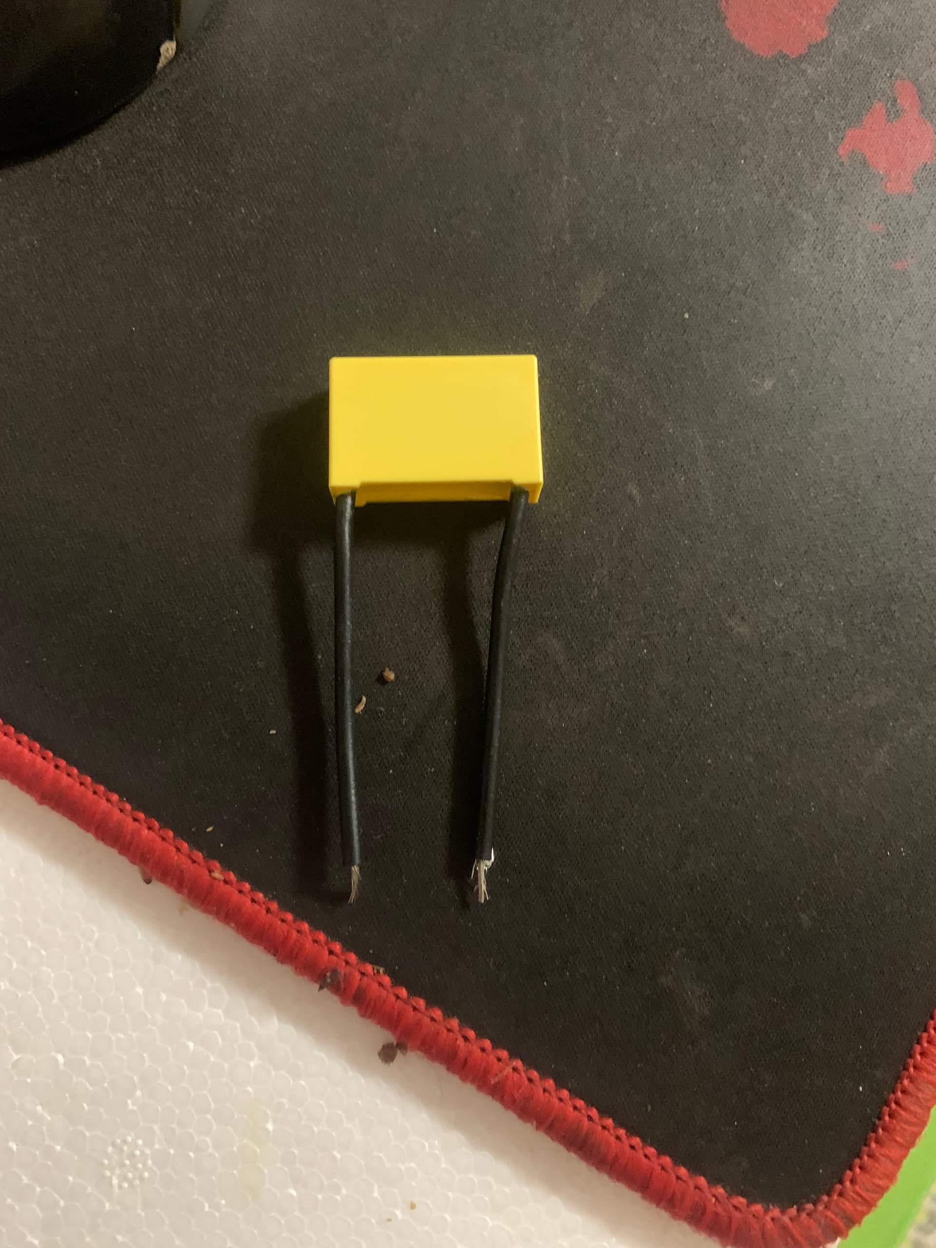
The capacitor goes across the two terminals of the lamp. If multiple lamps, you only have to do this for one of them.
Let me explain the principle. If you put a multimeter on a capacitor (a nice large electrolytic one), you will see that initially it measures very low, and then the resistance (or really the impedance) goes up. On DC, which is what the meter uses, the capacitor charges up and as it charges up, it passes less and less current until it is “full”, at which point it theoretically has infinite resistance (in reality it will leak a little).
If you connect a capacitor to AC, it will constantly pass current as the polarity is always changing. If you make the capacitor small enough so that it can full charge within a half-cycle, then only a small amount of current is passed to charge the cap on each cycle, after which it becomes an infinite resistance.
This means you can use a capacitor, connected to AC, to pass a well defined amount of current on every cycle. Almost like a resistor… but the nice feature of a cap is that it doesn’t get hot like a resistor.
So, what the cap does (connected to the light), is allow a small amount of current to pass by the light. That allows just enough current to reach the other end of the Wi-Fi switch, so that the switch can power itself from the live (on the one end) and the small amount of neutral current (on the other end).
Edit: This is the circuit with the green arrow showing how the current travels:
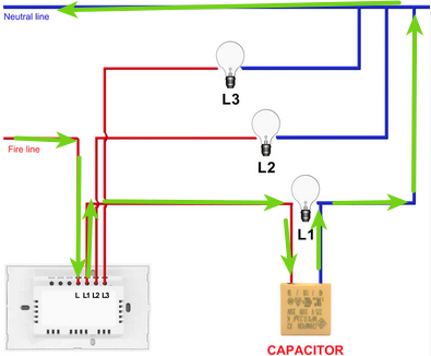
The capacitor ensures that a sufficient amount of current passes through the wiring at all times so there is enough power for the switch.
In some cases it might even work without the capacitor.
Also, you may find that LED lamps don’t fully switch off when wired like this.
Thank you Plonkster.
I will attempt this weekend and give feedback. I have 5 to do.
I suspect its going to get tricky as some of my lights has 2 switches. But if you say its only necessary to do it for each light bulb, then I should be good.
woah! You mean it is one light, with two switches opposite ends of the room?
You need SPDT (single pole double throw) switches for those. A normal single-contact won’t work.It is known as “three way switch” wiring, google it.
If you mean you have one switchbox and two lights controlled from there, then the capacitor only needs to be across one of the lamps controlled by the first switch (usually marked L1).
I am back, coffee next week? Ill prove not all electricians are bad. I still owe you an firmware upgrade for the freedom won.
Sorry for only responding now guys. I sustained a bad back injury and was in and out of hospital and seeing various specialists since 8 Jan. Still not fully healed so sitting down in front of a pc is really difficult and painful.
About 8 lights that all work from 2 switches in the different parts of the house yes. Both can turn them all on or off.
To be safe I had neutral wires pulled through from the lights to the switches, but one other light I did with the capacitor and it worked beautifully.
All that now happened was that one of the switches now does not work. Luckily not the crucial one. But that I will sort when I get to in time as I slowly upgrade all the switches.