I’m clueless when it comes to these things, but I’m assuming this is kinda the same topic:
Inverter heatpumps/aircons seems to be able to run at a range of power levels, up to a maximum. Now, wouldn’t an “inverter” geyser solve this problem, or an “inverter oven” for that matter.
I must admit, I have no idea what the “inverter” in the “inverter heatpump” implies, but it does seem to be able to smooth power draw after a required temperature was reached, to rather maintain gradually than blast it every few seconds (like my stove top…)?
Transformer inverters should handle dimmer loads better than others. That said, the specific case of a half wave rectified load is the very worst case for a transformer inverter - all the energy is in the tank circuit, and then the load is removed… Fortunately dimmers are symmetrical so this particular issue will not affect them.
Basically, they rectify mains to DC, then run an inverter off that DC supply to run the motor. I was actually contemplating the same thing yesterday - for a geyser you could simply run the element PWM off the DC supply, and it should work fine.
The problem is, a traditional rectifier will actually have worse load characteristics than a dimmer (the diode only forward biases at peak voltages - so peak currents are always at peak voltages). Current peaks will however be smaller. I see modern inverter appliances use a big inducter on the input to smooth/distribute the current load, so this could work here too.
I see where you’re going with that These “inverter” models are always for things that rotate. So again, I need to switch on teaching mode just a little bit.
It starts with induction motors. Induction motors are awesome little thing because they don’t have slip rings or brushes (at least the “squirrel cage” type doesn’t). The magnetic field in the stator (cage) induces currents in the rotor causing it to spin.
(Edit: In other words, the motor is also a transformer, with the rotor being the secondary winding).
But induction motors rotate at a constant speed for this same reason. They rotate at a speed proportional to the input frequency. So they have a very high starting current (to get up to speed as fast as possible) and then run at constant speed.
If you want to run them at a slower speed, you need to change the frequency. And this is where the “inverter” part comes in. You take the incoming AC, change it into DC… and then change it back to AC at a different voltage and frequency. This allows you to run the motor at a different speed, which means you can 1) avoid the huge starting current/torque, and 2) you can run a pool pump according to how much PV there is, or an aircon so that it’s just on the dew point where it is most efficient… etc etc
Microwave ovens are high voltage DC devices. In this case, ‘inverter’ ovens are actually more like modern power supplies - rectify the AC to DC, then ‘invert’ the DC to high frequency AC so that you can use a smaller (and cheaper) transformer. In the microwave’s case, you also have some ability to modulate the power through adjusting the output voltage. (Range is limited, as magnetron operating voltage range is quite limited.)
As I pointed out above - it is technically possible to use the same principle on DC, but the wins are negligible without a fairly advanced rectifier.
To me the interesting benefit of something like that is to bring down peak and erratic draw from appliances. This would make it much easier for a hybrid inverter to not overshoot the draw in the house and also put less strain on it. I can’t imagine it is good that a stove top draws 2000W for 5 seconds and then 0W for 15 seconds almost continuously throughout its operation (I’m making up the seconds here, but it is very erratic).
Oddly enough, in most cases, it is far easier (lower stress) on the inverter to switch 2000W on and off every couple of seconds, than to run a lower regulated load.
Most load regulator designs out there end up effectively turning the load off and on 100x per second, so the inverter ends up driving an snubbing load continuously.
You need to use a fairly advanced rectifier to deliver a constant load - which is possible, but is rare in all but the more expensive appliances.
So, while AC is great to transform and transmit power, is there an argument to be made to just have everything at the end user’s house run on DC? All electronic appliances really want DC. Resistive loads probably couldn’t care. Guess the only thing that is left are induction motors like refrigeration, aircon, pumps etc.?
I had the same idea a few years back. It turns out that DC has much more losses over a cable length that AC, which in turn mean you need to install much thicker cables which is much more expensive.
It’s the reason why Edison’s DC transmission did not was overtaken by Tesla’s AC transmission.
Some interesting reading Nikola Tesla - Wikipedia
So even in a regular size home it would lead to significant losses? Because at the moment we are dealing with at least 10%-25% of losses in all our electronic equipment (I’m sure there’s losses in other areas are well)?
Guess the interesting question is, long term gains (more efficient power usage in home, cheaper appliances) vs. short term losses (expensive cabling)…
I think you have it the wrong way around. DC losses are lower than AC (in fact, many long distance transmission lines are now DC).
Transmission losses are lower for high voltages though (lower current for same power), and AC is very easy to change the voltage (just pump it through a transformer).
Before the advent of modern hexfets (and even more advanced structures since then), this was still the case, but now pretty much all low power voltage conversion is done through either high frequency transformers or direct switch mode conversion.
So it would indeed make sense to use high-ish DC voltages (around 90V DC) for household power distribution. Most modern electronics would actually work fine off 90V DC. Non-inverter motor driven products would still require an inverter though.
You’re both right to some extent. Some assumptions are being left out of the discussion.
AC losses are higher when you use the same (RMS) voltage. But DC losses are higher when you use a lower voltage (which is what most people do). If you were to run a 230VDC system in your house, the cabling would be the same size, but the switches would be bulkier and much more expensive. Plus it is much harder to drop 230VDC to a lower DC voltage (which the appliances want). Well, these days everything uses an SMPS anyway, so perhaps that is less true now than it was 20 years ago…
Edit: Also, induction motors want AC. Making AC from a DC distribution network is harder than the other way round. And induction motors are significantly more reliable than anything with brushes. To the extent that many farmers have told me they’d rather use a “city” fridge and an inverter than the more expensive “DC” units built for the off-grid market…
Hmmm… These days, just about everything that operates at low voltage effectively uses DC. The input to just about every modern power supply is a rectifier to provide a 380V DC supply. This is then inverted to high frequency AC and shoved into a much smaller (cheaper) transformer than would have been required for 50Hz AC.
The days of clunky old 50Hz AC transformers are numbered.
I guess it has a lot to do about the usage of an item or idea on how effective it will be, and also the up take by the populous making the thing cheaper to produce and use.
To get back to the thermostat heading, I am thinking of looking for a way to use the Load relay/switch in my SmartSolar to switch on a load.
There is no option that I can see to make it usable under the ESS-> Relays section, however there are options under the VictronConnect in bluetooth to switch it, so there must be a way.
If it is available somewhere under dbus in the ESS this woud be perfect.
The vreglink interface is insanely powerful. You can actually fully configure all settings using just that. When supporting a customer, it is really useful to fetch the configured charge voltages… and even change it if you need to
Just joined the Forum, and thought I will share how I stored the excess solar energy into my geyser,
I had two 150l geysers for each of the bathrooms not too far from each other, one also feeding the kitchen. I wired them in series and installed in the first geyser that feeds into the second geyser a 1kw element. The Second (main) geyser now feed both bathrooms and kitchen at slight loss due to longer pipe runs.
Both have Geyserwise on for visual monitoring and control as well…
I then wired a Sonoff (tasmota) with temp sensor in parallel to the Geyserwise on the first feeder geyser, any hot water in this geyser will now feed into the main second geyser providing pre-heated water. this second geyser is still running on normal utility with 3kw element controlled via geyserwise
I have an axpert 5kw inverter with 4kw Solar pv array, and using Rpi4 with ICC and Node red.
I then used the node red and info from the ICC/Axpert to see when ever the solar input is higher than the load for a period (aprox 2 min) if it is i then, via sonoff with temp sensor, switch on the geyser and monitor again for 2minute, if the solar drops below the load then I Switch off the geyser again.
I have additional rules in Node red that will not switch on if temp (received from sonoff via node red) is too high already , and controlled output to ensure this geyser element is off during evening.
Using this i have seen the feeder geyser heat to 80+degrees.
This was the best way I could find to utilise spare capacity on the Axpert that would otherwise have been lost.
I am however in the process of replacing the Axpert with inverter that supports blending to better utilise the PV capacity.
@justinschoeman thank you for your code, i bought a geyserwise thermostat and implemented my own version with what you have done. Im curious, have you bothered to look at your temps during usage and what it looks like?
Generally get to 80°C every day, and have a loss rate of about 2°C per hour. A decent shower uses about 10°C. Can basically just store enough in a 150L geyser for 2 showers, and still have 40°C water in the morning.
I have a similar loss rate, however I cant say a shower/bath uses only 10°C yet. Ill have to monitor it some more. I have the NTC and also fitted a DS18B20 onto the flange as a second reading. I know there is some loss in measuring the flange, but the data tracks correctly.
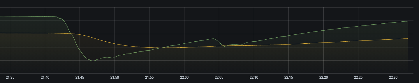
This was my wife taking a bath earlier, green line is the NTC, yellow is the DS18.
Drop measured internally is about 30°C, but the element sits towards the bottom of the geyser, the inrush of cold water affects it more down there.