Smart thermostat

I have recently been looking into using a geyser to store excess solar energy.
For a 150L geyser, each additional 5°C that you raise the temperature ‘stores’ about 0.9kWh of energy. So raising the temp from the desired 50°C to 80°C can ‘store’ 5.4kWh.

Of course, geyser heat losses increase with temperature, so it is quite a leaky bucket - but it should be possible to store enough for evening use, and still be fairly warm the next morning.

(NOTE: For safety, a tempering valve must be installed in the geyser if you do this, or you run a serious scalding risk from hot water taps!)

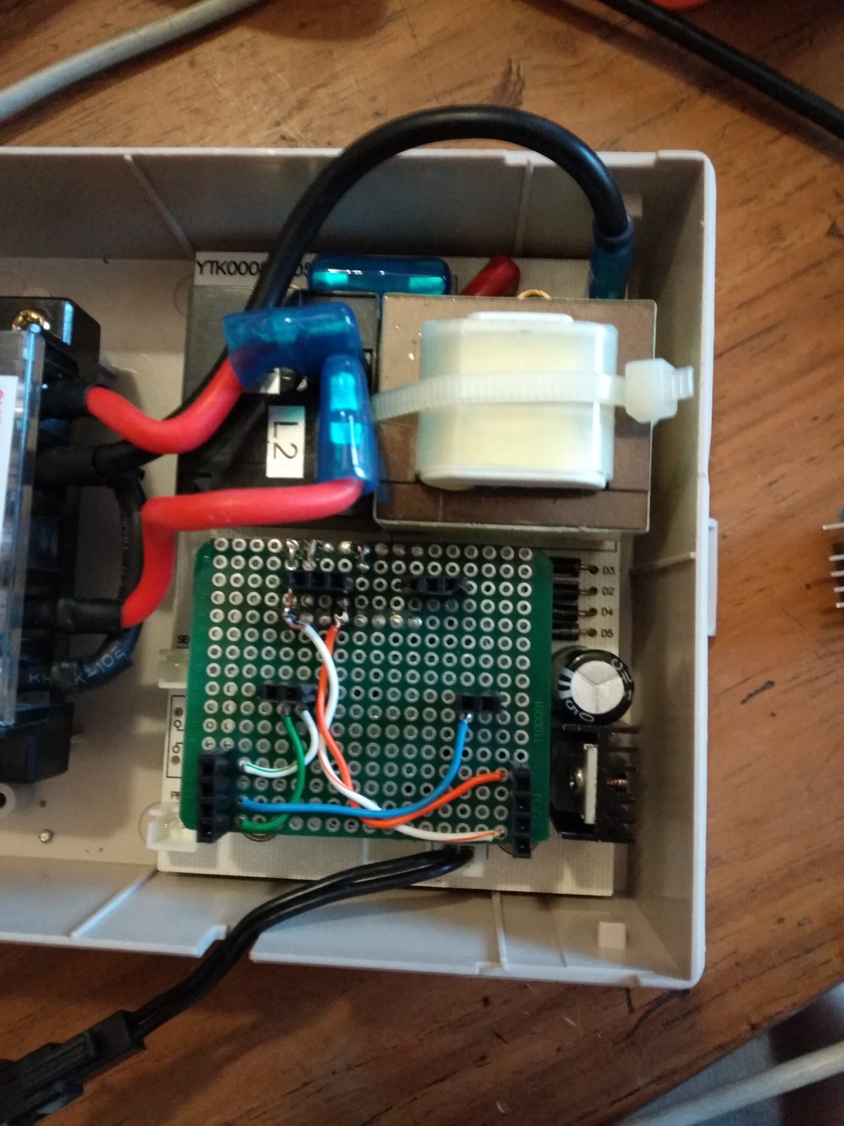
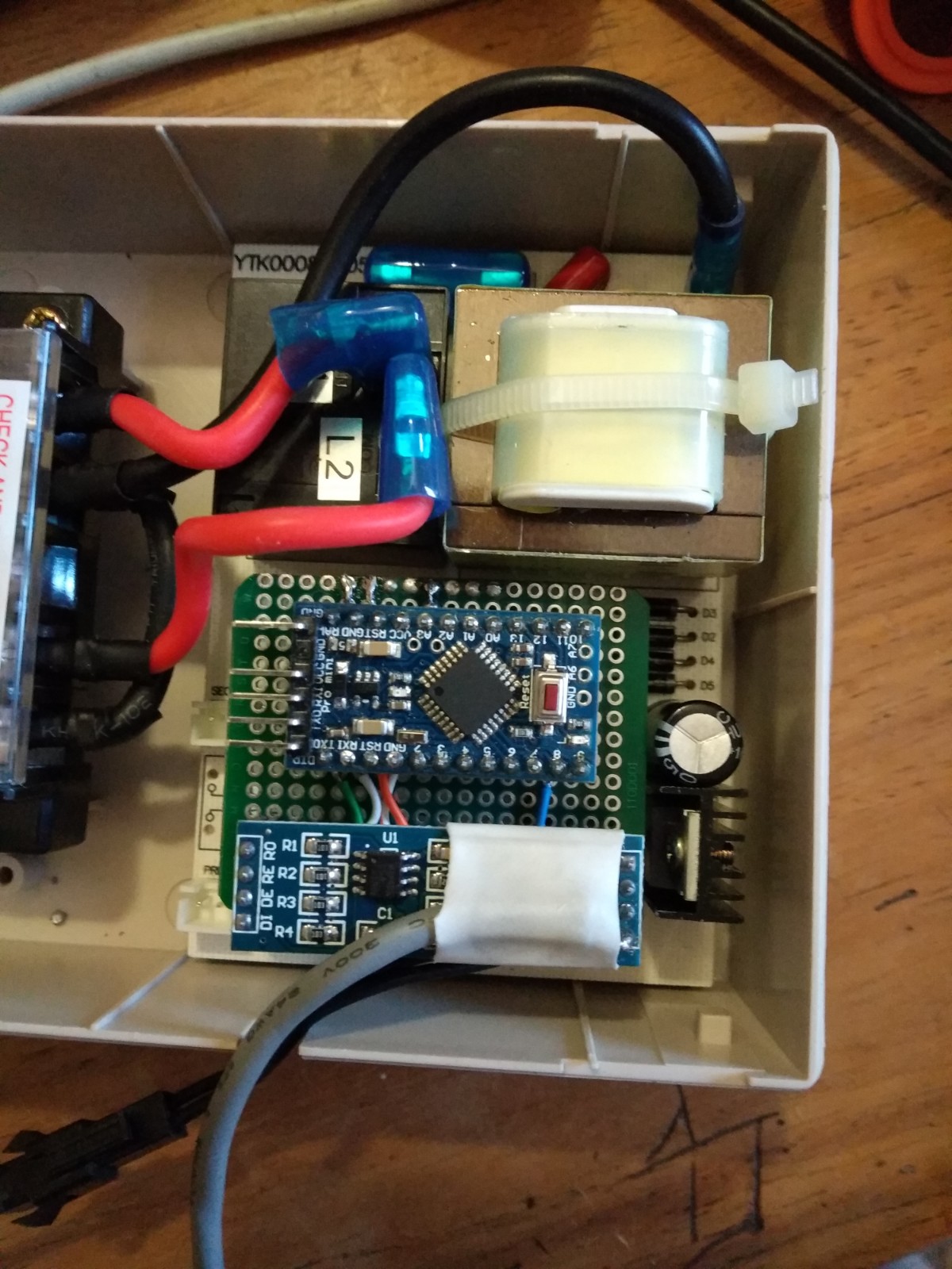
The first step towards this, is a smart thermostat, which can talk to the inverter, and ramp up the temp when excess solar production is available. I was initially hoping to use a Geyserwise controller, but it proved trickier than expected to reverse engineer the comms protocol. Instead I have desoldered the MCU, and am replacing it with an Arduino (basically using the Geyserwise PSU, temp probe + signal conditioning and relay).

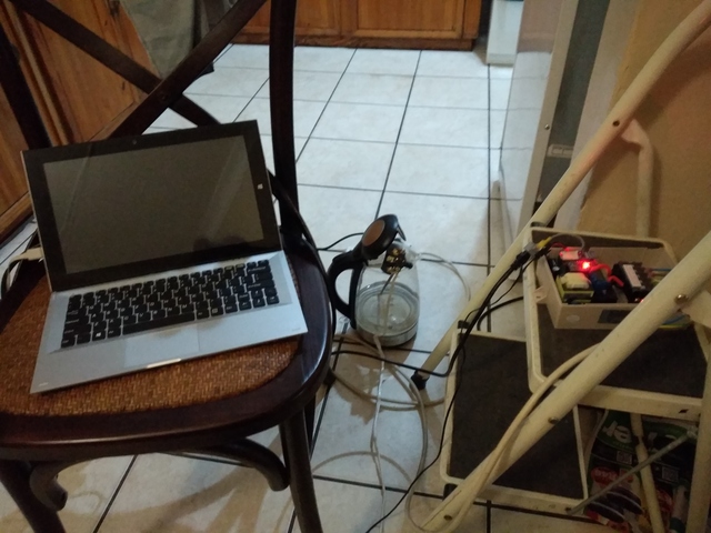
I am right at the very start of this project for now, but here are the bones:
geyserwise

https://github.com/justinschoeman/ModbusThermostat

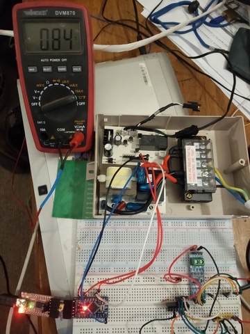
Right now I just have an Arduino powered from the Geyserwise PSU, and reading the Geyserwise temperature probe.

Will be adding relay control logic, and an RS485 Modbus interface for reading the temp and setting target temperatures.

5 Likes

Looks cool.
When I automated the geyser I had the same idea but ended up adding a “Parallel/Serie” system.
I placed a contactor in series with the geyser wize - in fact I have a different name controller but the principal stays the same. Then I have a ds18b20 temperature sensor placed in the geyser that measures in parallel with the geyser wize.

The advantage of this is that the Geyser wizes is still the “master” override should something go wrong on my side , but I have full control over the switch if it falls within the speck of what the geyser wise was setup.
The contactor is running from a atMega connected to my system via MQTT and is controlled though some java script (Node red) this also gives me the advantage that I can change the rules on the fly.

What I would really like to do is have some sort of way the control the geysers load similar to a pwm where I could match the out put of the solar to the load of the geyser. I read somewhere one could do it with a triac and a uno but it seemed to be a bit higher grade for my skills. The commercial stuff that I saw was very expensive 10k or so…

Of course one can also hook into the existing NTC sensor. If you use something with a very high input impedance (an ancient component such as the LF351 op-amp/comparator comes to mind), and assuming the Geyserwise does the usual thing of a simple voltage divider, you could easily get a temperature reading from that.

The problem with daisy chaining the Geyserwise (or any other thermostat for that matter), is that the Geyserwise can only go up to 65°C (and most others up to 70°C), which does not reach my storage target.

The reason I started out with a Geyserwise in the end, is that the temperature probe is a 2-part unit - it has a temperature probe for electronic control, and a mechanical 90°C thermostat for a safety cut-out.

The Arduino software I am working on will have hardware watchdog with fail-off capability as well for added safety. (As well as configurable paranoia settings to either fail off, or to a safe low temperature if comms are lost.)

In the end, analog control (via a triac dimmer) will definitely be the goal (and this hardware is extendable to do that), but such a system should include a relay override anyway (triacs fail closed, and would leave the geyser element permanently on). So either way, all this hardware will be used.

Geyserwise input schematic is at the top of https://github.com/justinschoeman/ModbusThermostat/blob/master/temp_geyserwise.h.

You would effectively be taking it off the divider before the low pass filter - so you can add your own low pass filter and ADC. Can even use the same conversion algorithm to get the temperature from the result.

/*
 * Geyserwise input/conditioning:
 * 
 *    ------- 5V
 *       |
 *       /
 *       \ 10k NTC
 *       /
 *       \
 *       |      1k 5%
 *       + ----/\/\/\-----+ ---------> PIN 32 (MCU)
 *       |                |
 *       /              -----
 *       \              -----
 *       / 3k 1%          |   10uF ?
 *       \                |
 *       |                |
 *    --------------------------- 0V
 */

// analog pin for temp input
#define TEMP_PIN A0
// Thermistor R@25C
#define TEMP_R 10000.0
// Thermistor B val
#define TEMP_B 4200.0
// Kelvin offset
#define TEMP_K 273.15
// 25C in Kelvin
#define TEMP_REF (TEMP_K + 25.0)

// set up temperature module
void temp_setup(void) {
  // default pin config is good
  //pinMode(TEMP_PIN, INPUT);
}

// smoothed temp voltage
uint16_t temp_val = 0;
int16_t temp_c = 100;

// internal function to calculate temp from ADC val
void _temp_calc(void) {
  uint16_t t = temp_val >> 6;
  double v = t;
  // to voltage
  v *= (5.0/1023.0);
  // to current through 3k resistor
  double i = v / 3000.0;
  // resistance
  double r = (5.0 - v)/i;
  // calculate temp from r
  double c = (TEMP_B * TEMP_REF);
  c /= TEMP_B + (TEMP_REF * log(r / TEMP_R));
  mod_temp = c - TEMP_K;
}

// read/smoothe temp and update calculation when it changes
void temp_read(void) {
  uint16_t tmp = analogRead(TEMP_PIN);
  uint16_t old_temp_val = temp_val;
  temp_val -= temp_val >> 6;
  temp_val += tmp;
  if(temp_val != old_temp_val) _temp_calc();
}
1 Like

I was going to ask in your geyserwise comms thread why geyserwise, other than
a) already have one and/or
b) the challenge/satisfaction of reverse engineering and modifying

any case, keeping in mind I do not know a voltage divider from a highway divider, I started looking into the whole geyser on a Sonoff thing, but being weary of “murphy” and his law enforcement possy I am not keen on losing the 90°C cut-out. … long way round to I started wondering about using <choice of “controller” … sonoff in my case> + ds18b20 + contactor + N.C. 90°C resettable thermal fuse ( example 1 , expensive version , candy store )

Idea would be to have the thermal cut-out cut power from sonoff to contactor coil (i.e. do not need to make provision for the current of a normal geyser element cut-out). One problem is most likely that these cut-outs seem te measure 7mm wide…my kwiktherm T105 thermostat probe measures 6.2mm and I suspect the geyser thermostat pocket is just not going to be big enough.

No idea how easily a contactor will fail closed but I suspect it is much less likely than a relay on a sonoff doing it

There is someone I know who wrote cool software that uses a Venus and a BIG relay to control/manage when geysers can come comes on/go off, based on a number of parameters.

Have invited him to join use here and share what he did as it would be a nice addition to the other efforts here I believe. Software was free.

I’ll push him a wee bit if I must … (evil grin emoji goes here)

2 Likes

No swearing on the forum please… :laughing:

3 Likes

Fixed! :laughing:

Oops - missed this post entirely…

The simplest solution is usually the best solution. Technically, you can make a thermal cut-out work - but their current capacity is too low to put them directly in line with the relay. So then you have to start looking at adding relay chains/transistors/etc. Eventually adding lots of complexity. But the goal of this cut-out is safety, and complexity and safety are generally mortal enemies.

In the end, the best option I could find is a geyserwise thermostat with built-in cut-out. Solid, well tested and reliable. Contains a built-in temperature probe, and you can pick them up at a plumbing store for around R200.

In the end, I bought an entire geyserwise controller, assuming I would be able to reverse engineer it, and use it as-is. That did not work out, so I just use the hardware I can. Between PSU, relay, enclosure, etc the cost difference is not that big.

Software more-or-less ready to install:

https://github.com/justinschoeman/ModbusThermostat

Added documentation on the geyserwise relay circuitry. Lots of paranoia/watchdog code to make sure the relay turns off if anything goes wrong. (Although you can disable most of it, if you just want a dumb but controllable thermostat.)

If any knowledgeable person is bored, I would love a second opinion before it goes in the ceiling :wink: .

1 Like

Very cool @justinschoeman
I’m trying to figure out what electronics is required for this build.

I’m a very lazy developer, so I like pictures :slight_smile: and tried to figure out your hardware from the picture in your OP.
If I am correct you have a Arduino (Nano?) as the controller.
Can’t see the 2N5551 Transistor, or is that part of the Geyserwise board?
I also assume the Geyser relay coil is from the Geyserwise board.
Do you use a normal TTL->RS485 converter for the Modbus stuff, hooked up to the Arduino pins?

Maybe a parts list and circuit diagram would be great.

i will post some better diagrams later - need to get the hardware installed before @JacoDeJongh does the plumbing on Monday…

The hardware is basically just a Geyserwise TSE controller + thermostat. I have desoldered the MCU from the board, and soldered a socket in.

I will plug a daughter board into that socket. This board will contain 1 Arduino (Pro-mini in this case, but just about any small board will work), and 1 RS485-TTL converter (the current code requires an explicit direction control pin, but this can be modified).

Hooking up the RS485-TTL board is just TX->DI , RX->RO, VCC->VCC, GND->GND and 8->DIRECTION.

Hookups for the Arduino are pin->pin with the Geyserwise MCU (pin mappings are in the source files).

NOTE: You don’t have to use the geyserwise board - it is a very convenient PSU, and has relays and analog conditioning built in - but this can easily be replicated.

Bare Geyserwise board - MCU and secondary relay removed.

Through pin headers soldered in to the required MCU pins. (NOTE: MCU has 1.78mm pich pins, so only every 3rd pin lines up - the in-between ones need to be bent one side or the other to go through one of the 2 MCU holes - choose carefully, because you need 1, 5 and 26!)

1 Like

Bare daughter board in place. Sockets for required Arduino pins and RS485 converter pins in place. Point to point wiring for the few required connections.

Fully populated and ready to boogy:

1 Like

And just to test it all out, a thermostat controlled kettle…

kettle

2 Likes

I have the same step ladder. Unfortunately I never knew my real ladder.

6 Likes

Looking cool , well done.
How do you run the coms to your system or is it running isolated? (Just for incase I am not clear :smile: 
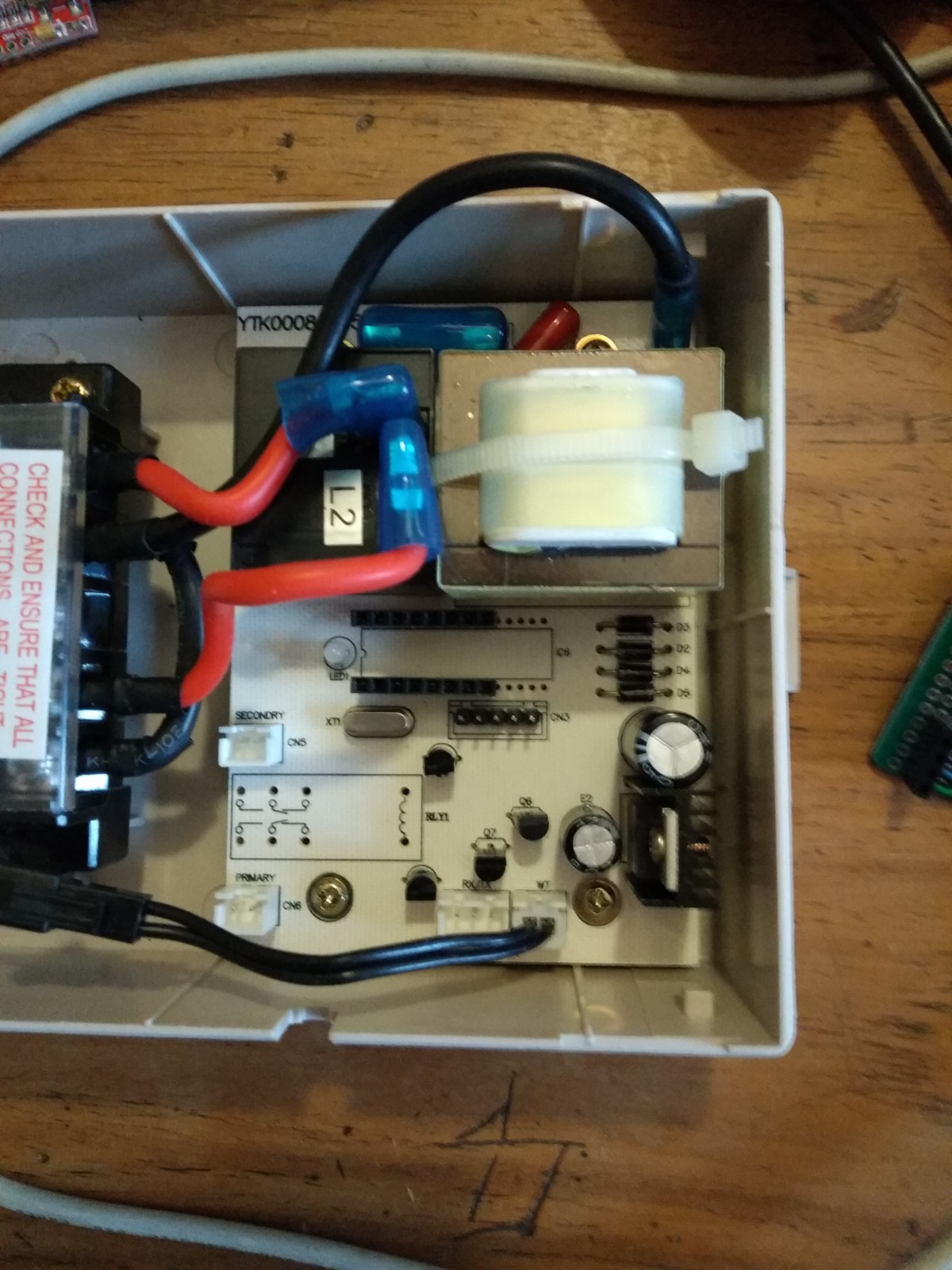
is the system sending the data to a server or not)
One thing that you might consider is to have some timers running rather than having the data pushed at the rate of the nano’s loop (117 kHz).
I see you placed a WDT in the sketch is that as a precaution or necessary. One thing that I have found is that sometimes the WDT does not get activated if the sketch are running out of memory as it is part of the program it self. So if it gets stuck in mid loop the WDT will no get activated.
One thing that does works for me is the monitor connectivity and should that timeout there is most likely a problem so reset then.
Again well done its looking good

1 Like
  1. It is an isolated system, although the master (which I will publish shortly) will eventually get an ESP-01 to make status available over WiFi.
  2. Comms are polled at max rate, but only acted on serial data is received. The only bit of code that actually runs on each loop is the ADC smoothing algorithm - but that must run fast to be effective.
  3. WDT is there for paranoia. It is a separate hardware WDT on the Arduino, which resets the device if ‘wdt_reset’ is not called regularly. So if the code stops for ANY reason at ANY point, the CPU will reset, and geyser relay will turn off.
1 Like