I am taking a wild stab at this here but is there someone that can rent out a Power Quality Analyzer, like the ‘Fluke 435-II Series of Power Quality Analyzers’ or even a service that does analyses that I can make use of?
I have a strange grid frequency disturbance that triggers my inverter to Invert. My Zhiel doesn’t pick it up and my own measurements point to a sudden and short frequency shift, usually only two or three cycles. My PC UPS picks it up as a sudden ‘click’ and then immediately after another ‘click’ and then all is back to normal. When I am in Bypass Mode (C/O Switched to Grid rather than Inverter) I don’t notice it at all, no flicks of the lights nothing, just the UPS ‘Click/Click’ and the Inverter going to Inverting Mode and soon afterwards back to Grid.
Buying one of these analyzers is too expensive to satisfy my curiosity - and I am WAY curious about this. Maybe someone working for Eskom or other consulting firm to Eskom could give me some pointers. I have even thought of giving the CSIR a call to hear what they recommend I can do or try. The normal sparky’s don’t usually carry such expensive equipment in their arsenal, it’s specialty kit for engineering consulting firms if you ask me.
@plonkster@mmaritz No, not geyser control or DC ripple as it lasts only a fraction of a second and a week or two can go by without this happening and then it can be as bad as two or three times per day.
Checking on a zero crossing detector I can see the frequency change in two or three cycles and then it’s back to normal. If I had a fancy storage scope I could have captured the wave but I am old-school and still have one of those that take up the whole bench type scopes which doesn’t store anything.
Even then, you’d need a pretty good mechanism to trigger the scope. Though if you already have a way to monitor the timing of the zero-crossings, you could possibly use that. but my point is that even people like myself who have a scope would need to do a lot of work to get the info…
You are right, I have a trigger. My cct has a very consistent 0.92ms pulse between the positive and negative halves of the wave. In every ‘glitch’ this value goes >1ms and I have my logic analyser watching for those. It’s been a 100% hit rate like that. If the scope can trigger on a level longer than 1ms then a storage scope would work for me.
From the analyzer I can see the the wave getting ‘longer’ meaning the frequency is dropping and it really is only one or two half-cycles that triggers the inverter. I would love to see the actual wave deformation. Looks like I am going to start searching for s storage scope, it’s cheaper than that Fluke.
Scopes usually trigger on level. But you could build a simple RC network on top of it, so that the capacitor charges through a resistor, and would theoretically each a higher level if the pulse is longer. Or, perhaps simpler, just use an arduino or something to monitor it and raise an alarm, which can then trigger the scope.
But since you don’t have a scope yet… maybe you can build one using an arduino… which means that with a bit of code you may be able to build your own. Eg this guy…
I’m not really helping by coming up with ideas, right?
Well, I am open to any suggestions. I actually looked at an Arduino scope idea a while back but got stuck on the displaying of data on a high-res display in realtime. The idea is to go 12-bit ADC to really capture lots of data but screen updates are usually too slow. I then didn’t really investigate further so should perhaps just give it a bigger time slice of ye’ol brain to come up with a solution as logged data is more important than realtime - I can display it offline.
Certainly, a very good scope can be had for under 350 USD nowadays. Siglent makes a good 2-channel scope for 260 USD now, and the Siglent SDS1104X-E (which in my mind is now a better value for money option compared to the Rigol DS range that used to be the choice entry-level scope) is only 499 these days.
But for a hobbyist, that is 7k or more. I do however see very affordable options from Hantek.
Also, I have been unable to find local Siglent stockists. You’ll have to import. There is an outfit up North that sells Rigol.
I personally pulled the trigger last year and bought the cheapest Keysight on the list. Apparently you can hack the divider bridges and upgrade it to something better…
Agreed, that looks to be a bargain. If I didn’t buy the last PicoScope from RS yesterday this would’ve been great. That said, the PicoScope software allows me to trigger on complex wave patterns, perfect for ‘waiting’ until my pulse width goes out-of-scope (pun intended).
The automotive people love their Pico Scopes. These days a good auto technician needs a scope, to check cam/crank signals (basically rotary encoders), do a relative compression test, or check healthy can-bus comms. I’m sure you will love that thing. I almost bought one, then went for the Analog Discovery instead, and after a major screwup in the order, cancelled that and bought the KeySight in the end. So instead of buying the 2-3k one I ended up upselling myself into a 9k scope… the hazards of tool buying I tell you!
Yes, thanks. Even though a normal scope requires more setup to actually try and catch the glitch it’s probably 5x or more less expensive than a dedicated power quality analyzer. Plug and play analyses would have been nice but let’s see what I can find using my scope.
I have a Fluke 41B power analyser.
It’s not the latest Fluke offering but it was used to check the harmonics on a supply.
I can’t upload the manual but let me know if it could be of use to you…
Thanks for the offer Richard, I had a quick look at the manual online and it looks like a real-time only tool without some sort of trigger that can sit and wait for an event. It’s also good that I purchased the Scope then instead of an expensive Power Analyzer as I now see it might not have been the right tool for the job.
For those wanting some feedback on my investigation… I’ve been waiting for my ‘glitch’ to appear for a while now and the only two times I caught something it was a proper brown-out and not the ‘glitch’ I was hoping for. In the meantime I noticed something very interesting, Grid power is well, hmm mostly very clean apart from a minor hiccup every now and then - nothing too serious as nothing except my Scope detects, or is affected by it.
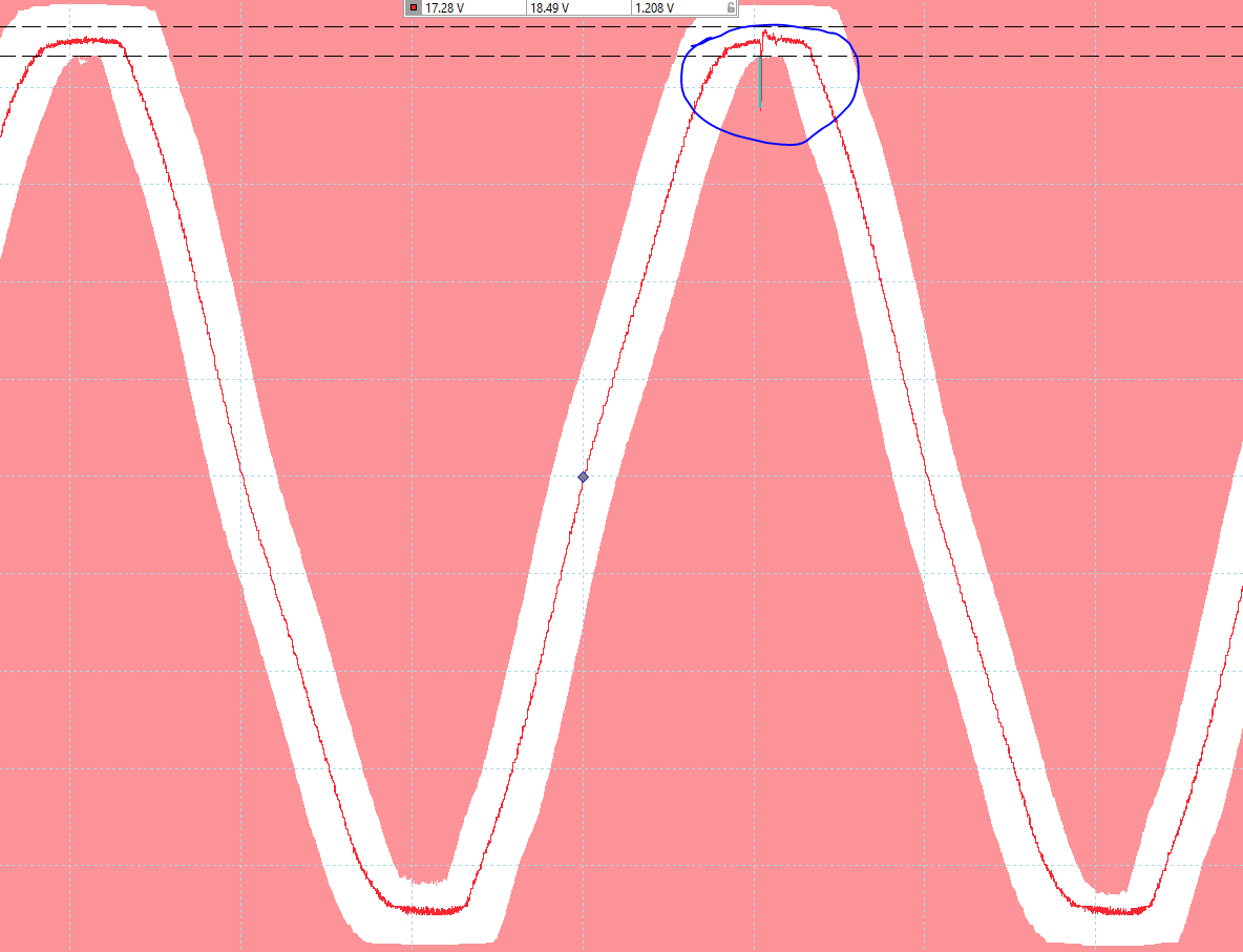
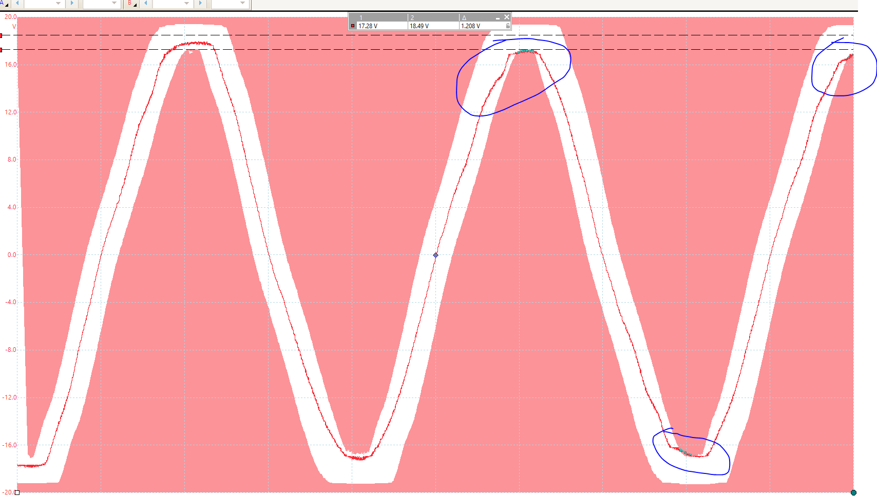
While I am in a loadshedding cycle I also saw the Multi’s sine wave which is not as good as the Grid wave. It seems to ‘float’ around a bit like a loose string in the wind, with Grid being a tight string - if you know what I mean. Here is a sample of my Multi’s wave with only my PC UPS clicking on|off if the voltage drops into my configured mask area. Again, nothing else is affected by it.
It’s probably a fridge starting up, but notice the shape of the wave, really looks like an ever so slightly ‘loose string’. I thought it might be my digital scope sampling that does this so I got my old heavy scope out the cupboard and it shows the same - nothing wrong with it, just very curious indeed.
Indeed. The grid has a very hard signal, and no inverter will get close to a good grid-, or even a industrial size Diesel generator’s quality. What you see there is the physical representation of the THD (total harmonic distortion) figure on the spec sheet. The Multi has a worst case THD of 5%, which is less than most petrol generators and about on par with a good Diesel generator.
It is interesting that the distortion is at the peaks. This is where the PWM signal has the highest mark/space ratio, which may have something to do with it.
Something else you may also sometimes see is little flat bits around the zero point: That is usually because of a small voltage drop in the switching electronics… eg if you were using bi-polar transistors to do the switching (which you might, an IGBT is combo FET/bipolar transistor), it may not be possible to reproduce the first 0.7V or so of the ramp, so you’d have these small flat spots which then jumps up. That also contributes to THD and is completely normal.