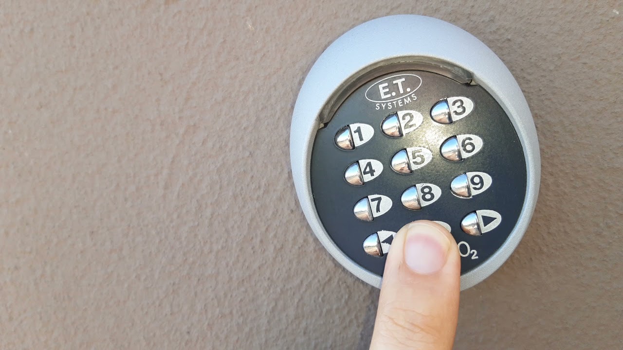
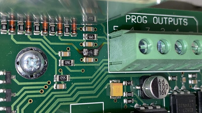
Sooo, I had some time to tinker with the IDS X-series. The installer code is indeed left to the default, so that was easy enough.
Then I tried programming it to turn on a programmable output. I think I’ve succeeded, but I will only be able to check tomorrow.
First I was directed towards location 414, which is for “Arm follow programmable output event”. This was already set to 34, which is the PGM output on the first keypad, which happens to be where the present indicator LED is wired to. Since I can only have one PGM attached to this event, it would mean tapping my sense wire into the LED feed. This has one additional issue: When the alarm triggers, the LED flashes, and that ends up writing numerous on/off events to the HomeAssistant database. Not ideal. I was looking for something cleaner.
Then I noticed that locations 390 to 392 involves “Close” and “Open” events, which is not really fully explained but the documentation about the logging suggests these are arm and disarm events. 390 is already programmed to set PGM3 high, and 392 is programmed by default to set it low. After spending some time figuring out how to read the BCD on the LED keypad, I also configured 391 (stay arm) to set PGM3 high.
The confusing part about the BCD display is that you read it in BCD, but you don’t “write” it in BCD. For example, to set location 391 to 0300 (where 03 means PGM3 and 00 means set it high) is done by typing:
9999*391*1*0300*
After doing that, LEDs 5 and 6 are on. I eventually figured out that this is because LEDS 1-4 is the first digit (zero), LEDs 5-8 is the second digit (3), and LEDs 9-12 and 13-16 are the last two digits, (00).
If you type 9999*390*1* to view location 390, it has LEDs 5, 6, and 13 on, which reads 0301.
So now hopefully, I will find tomorrow that arming the alarm gets me a 12V on PGM3.
Edit: Also, a Sonoff SV fits neatly into this enclosure. I added an opto-isolator this time to drive the GPIO too.


