Yeah, trying to figure out what they mean by some of these things are confusing. I am not following the part of the BCD on the LED keypad as I have the LCD keypad and that by itself is a mission to follow if you don’t see a command through. If you stop and look away you easily lose track of where you are in the command.
Location 390 and 391 sounds familiar and I will need to check what locations I have changed. I think I used PGM1 high for Stay and PGM3 high for Away ( I think it was called the Close event). PGM1 was used for Panic or something, but I changed that. I think it was assigned to location 403. Then there is a location 380 or something which I used to set both these PGM to Low on disarm as the Open event could only set one output to low.
What value series resistor are you using to drive the opto? Are you using the SV relay to do the away arming?
Yup, that’s a bitmap for which things to clear on disarm. Looks like I won’t need it, cause 392 should do the trick.
4.7kΩ. That lets through about 2.5mA, which is what the opto wants according to its spec sheet. I would have wanted to go a bit high if possible, but I was limited to what I had in the parts bin
Yes. So I can arm and disarm remotely, or disarm while still in bed on a Saturday (if the kids wants to go downstairs).
Nice low current draw. I don’t know why in this day-and-age they still use linear regulators on these panels. It seems to be very inefficient, especially if you feel the heat coming off the heat sink. Surely a buck converter would provide a lot more current. I am not sure if the high frequency switching will introduce noise though, but I feel it should be part of their design. Anyhoo, I am going off topic.
I just checked and I configured these locations in addition to the default PGM3 config if anyone is interested:
Disable Locations 401 and 405 for Keypad Panic and Duress output and add output 1 set high for location 391 when stay armed.
9999*
401100*#
405100*#
391101 00*#
and then to clear all programmable outputs on disarm
9999*
380*
1*
3*
My next project is to add beams to partition 2 and be able to arm them separately from the main partition, but not necessarily let them notify the control room once violated.
I can report that simply setting locations 390, 391 and 392 does the trick for me. But I don’t have a need to indicate both away- and stay arming.
The last time I tried this, I measured all the available PGM outputs, because I thought maybe one of them was already set up for it. I could not find one that worked. Then last night, while reprogramming the alarm, I noticed that PGM3 was already set up for this. I do not know how I missed it the first time. Oh well…
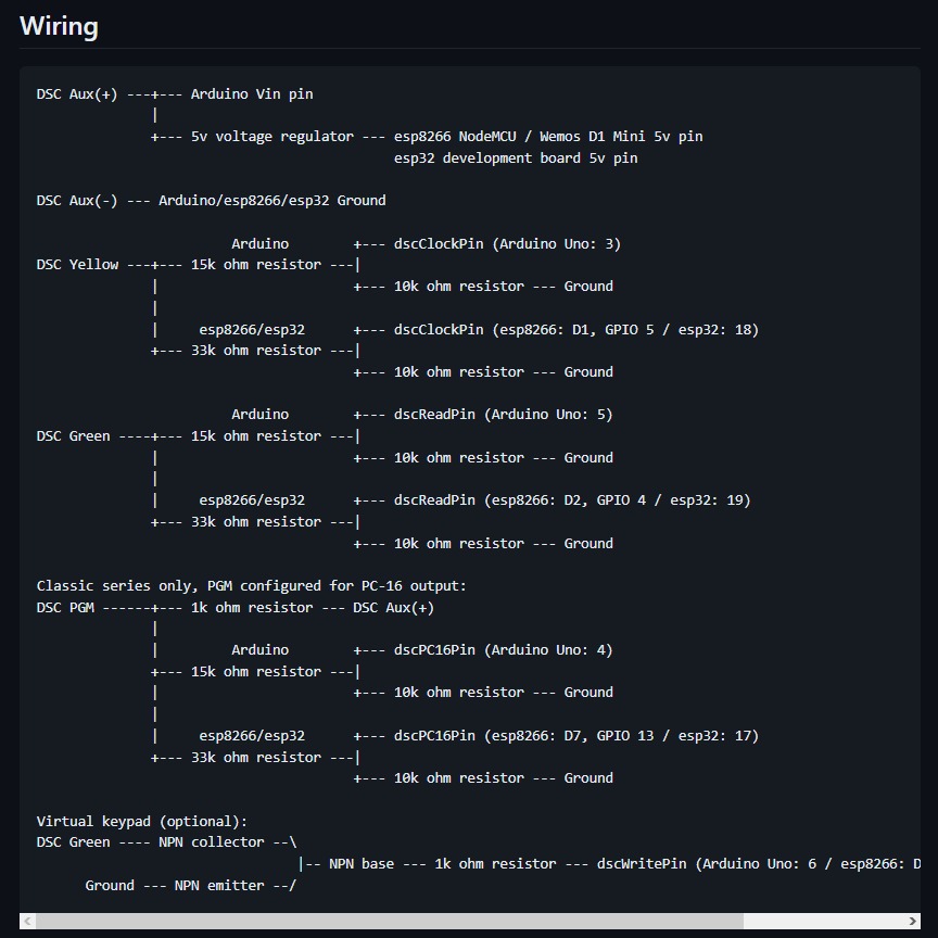
Has anyone got a wiring diagram? I’m planning on using ESP8266 to do my integration with my ancient ids alarm.
I might be really pushing my luck, but I would like to tie into my system to arm and disarm the alarm also I would like to see which zones are currently active ie. If a door is open
I currently have my home assist wired in the same as the attached as I didn’t read and just mistook my alarm for a dsc alarm