Download the reference ftdi driver and install it. For some reason Windows does not come with an ftdi driver by default. Well, sometimes it does, sometimes it doesn’t, it sorta depends. In my experience a stock windows 10 install on a virtual box… does not have this driver. And the best one is the reference one from ftdi itself.
All the Victron cables have an FTDi USB-serial chip inside. So installing that driver fixes it for all of them.
Thanks I think I got it right now. If you could confirm if this is correct.
I had to go to device manager and locate the MK3 usb device open it and update driver to the files that downloaded. It seems to have now renamed it USB serial port (com9)
edit: it worked it now picks up and access the multi. thank you
Just for interest sake I managed to make lengths 4m total with return. From battery to disconnector 60cm and then 90cm from disconnector to busbar, then from busbar to inverter 50cm so 2m each pos and neg. You will see a bit of slack which allows me to move and add batteries later without having to make longer cables.
After getting my MK3 working I have been fiddling with the ve.config program and got a couple questions. Currently I don’t have my panels or MPPT set up yet so do I still need to set up the ESS assistant as it keeps asking me to add assistant or delete the assistant part.
Also at first it was charging at 57+ volts which the batteries were giving warning so I set up DVCC and put in correct parameters and also set smart battery bms to give its info, but then in the ve.config it asked to set up alarm for low SOC and then it wont do that unless you enable battery monitor, after this it started charging weird again. Do I switch off all battery settings in ve.config and just let smart battery do its thing?
You dont need to, but i do set it up if I plan to add panels soon.
You need to configure it correctly. once you configure the charging volts it should be okay. there is also a setting you need to click in ESS that prevents the system from changing back to default values.
I am not good in explaining stuff in writing, but if you need help I can help you configure the system. Please PM if you want some help.
I’m going to take a look at the ESS assistant then. I will definitely ask for more help but going to try first on my own and see what happens and then get help. At least for now I can still run the house off mains while I change the settings. Now that you mention the default values i think that is exactly what it did.
In ESS, tick “Do not Change battery type”. In the normal config file, please remember to select Lithium batteries and then adjust the Bulk and Absorb voltages to the values supplied by the battery supplier.
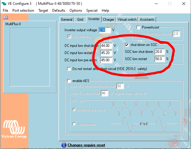
I’m a bit confused with this setting.
I thought SOC is determined by the voltage level so if you set it to min 20% doesn’t it mean that the voltage DC input settings to the right are not really needed? How is it determining that its at 20% does the inverter calculate that or is it taking the info from the Battery BMS?
You don’t need to worry about that, as the ESS will control it. That setting will only come into play when the GX fails and the Inverters own config file takes over.
So loaded ESS and changed some settings and its up and running. might still take up your offer to check settings @JacoDeJongh once I have my MPPT up and running. Right now its just on keep batteries charged as a ups. But I’m still to scared to switch on my critical loads until you explain the other post with the burnt multi.
So today a Eskom transformer decided to trip and the multi worked flawlessly all morning running the critical loads and only used 15% of the battery.
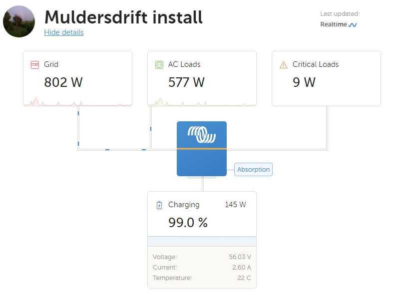
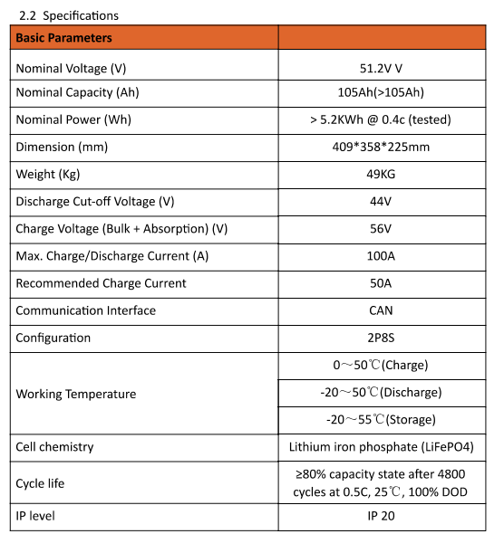
But one thing I noticed is that when it recharges it always goes from bulk to absorption but never switches to float even though it’s at 99% full at 56V as per battery spec, also it then shows that some cells are not balanced as some are at 3,3+ and some at 3,5+ if I manually change max charge voltage to 54V as per battery float spec then everything settles and cells are almost the same.
Why is it not dropping down to float setting and just sitting at absorption level?
Has it got to do with the keep batteries charged setting?
I would leave the Max Charge Voltage at 56V per spec and let things settle. The BMS will balance the cells that are low and I guess this will take some time. Float doesn’t really apply with Lithium Batteries (its a Lead Acid issue).
In the manual you see no Float Voltage even listed.
Thanks
I think what’s confusing is it has 54V float actually printed on the battery so not sure why. Cool that they can handle 3.65V per cell so will just keep eye on that. Batteries have only cycled twice so could also just need a deep discharge and slow recharge to get them nicely balanced
Cause it uses something called adaptive charging. The longer it takes to get it from bulk to absorb, the longer it remains in absorb before dropping to float. Of course this is more important for lead acid batteries (which needs some time to absorb charge and does so faster at a higher voltage).
For LiFePO4 there isn’t really so much of an absorb or float voltage. Many of the commercial BMSes only have one charge voltage.
As long as your highest cell is below 3.7V, I would not invervene by lowering the charge voltage. This is the ideal condition for the BMS to balance cells (taking charge from that high cell and putting it into a lower cell). By lowering the voltage until the imbalance disappears, you are actually impeding the balancer from doing its job. Over time, you should see the lower cells pull up and those high cells come down until they are all in line (top-balanced).
You don’t even need to go that far. Take them down to 80%, and then slowly take them up to 100% again. Also remember that no balancing is done unless 1) current is actually flowing into the battery, 2) one or more cells actually measure higher than the others. In other words, all of the balancing happens somewhere above 90% SOC once one of the cells steps out of line… so you want to spend as much time as possible in that zone.
Alternatively… just run the battery normally. It gets better every day on its own. Start by setting a charge voltage that allows your highest cells to be between 3.6V and 3.7V. Then as you see the balance improve, move the charge voltage up slowly by 100mV every few days… and just use the system normally.