Its the difference between isolating 1 battery or 3 batteries with one 3pole keto disconnector and will make a difference to cabling so the R90 saving now becomes R4000 or more saving if I only need one disconnectors instead of 3.
Just like you use 2 disconnectors for 3 multis ect
But I really am genuinely interested in what SANS says. If its common installation procedure then i will just use one disconnector per battery
I miss why you would need an isolator on each battery, but its your installation, that fuse will do exactly what your current build in breaker does. If you want to switch one battery of, use the breaker.
You fuse both sides if the system is floating, and there is the possibility of more than one ground fault.
The easiest starting point is a car, since we all know that well. A car’s electrical system is not floating. The negative side is tied to the chassis. A single ground fault (from a positive side to chassis) is therefore enough to cause a large “fault current” to flow and blow a fuse. So generally the fuses are only in the positive side.
Solar systems are usually not earthed, they are left floating. A ground fault could therefore occur on either side of the battery (without causing a large fault current, since you need two ground faults before that will happen), and for that reason you fuse both sides.
However, I am also of the opinion that under certain circumstances, you need only fuse the positive side. If your cabling is arranged such that a ground fault is extremely unlikely, then you fuse only one side to protect the cable against overcurrent.
But all of this is besides the point if the regulations want you to protect both sides.
Whatyamacallit, right back at the start when you asked for ideas, I suggested the Keto and fusing Pos and Neg using the 3rd pole for a MPPT.
Idea is simple, if you pull the fuses, like my case, the inverter + MPPT + Venus is dead i.e. DC side is disconnected from the batteries.
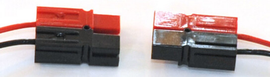
Only things that are still “live”, like in my case, is the BMS, BMV and the volt sensing wires, which I use small Anderson Connectors to disconnect them all from the batteries, like these:
BMS I unplug the balancing wires, and it goes off.
DC side is then totally OFF.
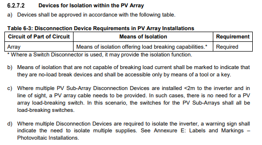
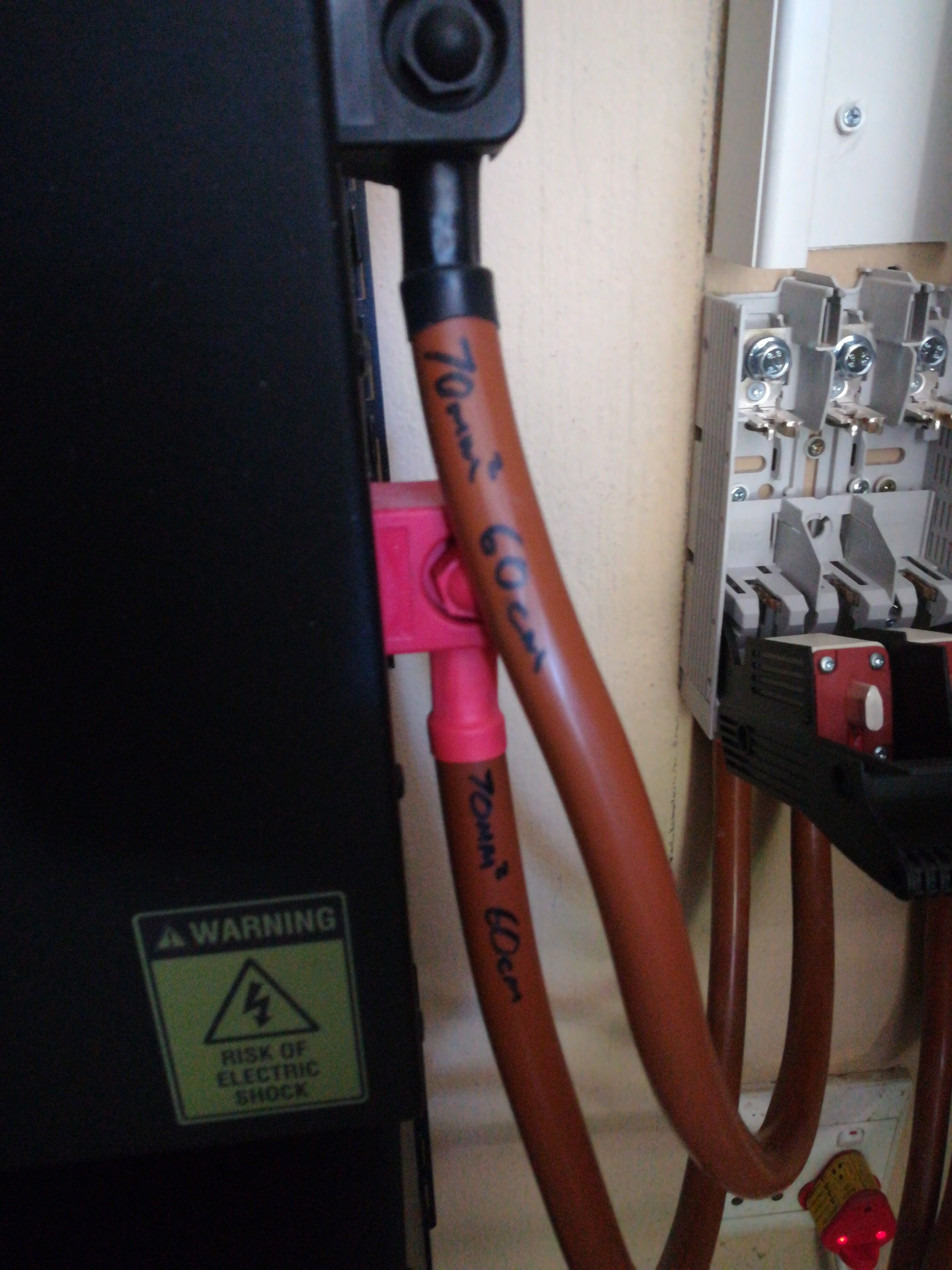
Connecting both batts to the bottom of the Keto, you can break out the thingies for a bigger hole, I HOPE both can fit onto the bolt, If I look quickly at mine, these 70mm2 cables we have ARE thick!
Please share if you find the SANS regs ito what must be done, but here is the thing - you have it so use it.
That’s how I understood it yes cause originally I did exactly what you suggested as additional protection in case the Venus “fails” or is switched off during peak hours when I had the Trojans.
Seeing the drop in peak potential production, I started to ask around. I was then told to leave the MPPT on its max charge amps and not set to the same as the Venus/Inverter is set to.
Now with the lithium’s and the 250/100 it matters not
I’ve done the same but like the idea of having a fall back if the Venus fails… especially if you have to manage a smaller bank or have overspecced the PV.
Saying that the BMS should sort all of this out anyway!
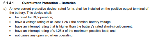
I found the SANS info I was looking for however I don’t have the latest 2020 edition 3 so if someone does they can confirm. I will post it soon and highlight findings. Its under 6.1 and 6.2
The above point refers to the single pole breaker on the battery interesting to see its only required on positive, but this means will need isolator if you see below.
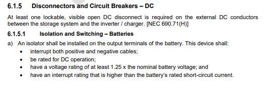
The above point refers to the isolator disconnector and has to be on both pos and neg, final note on 6.1.5 and see first bullet on 6.1.5.1 show that it must interrupt both cables so can’t be separate disconnectors unless they mechanically coupled.
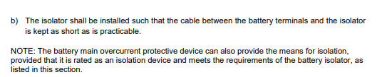
The above point c) refers to the isolator disconnector for every DC input. Here im not 100% sure if they mean one on each battery or bank or one just before invverter?
For pv DC inputs it has other regulations
PLEASE NOTE THIS IS NOT FROM LATEST 2020 ED3 SANS BOOK SO NEEDS TO BE CONFIRMED
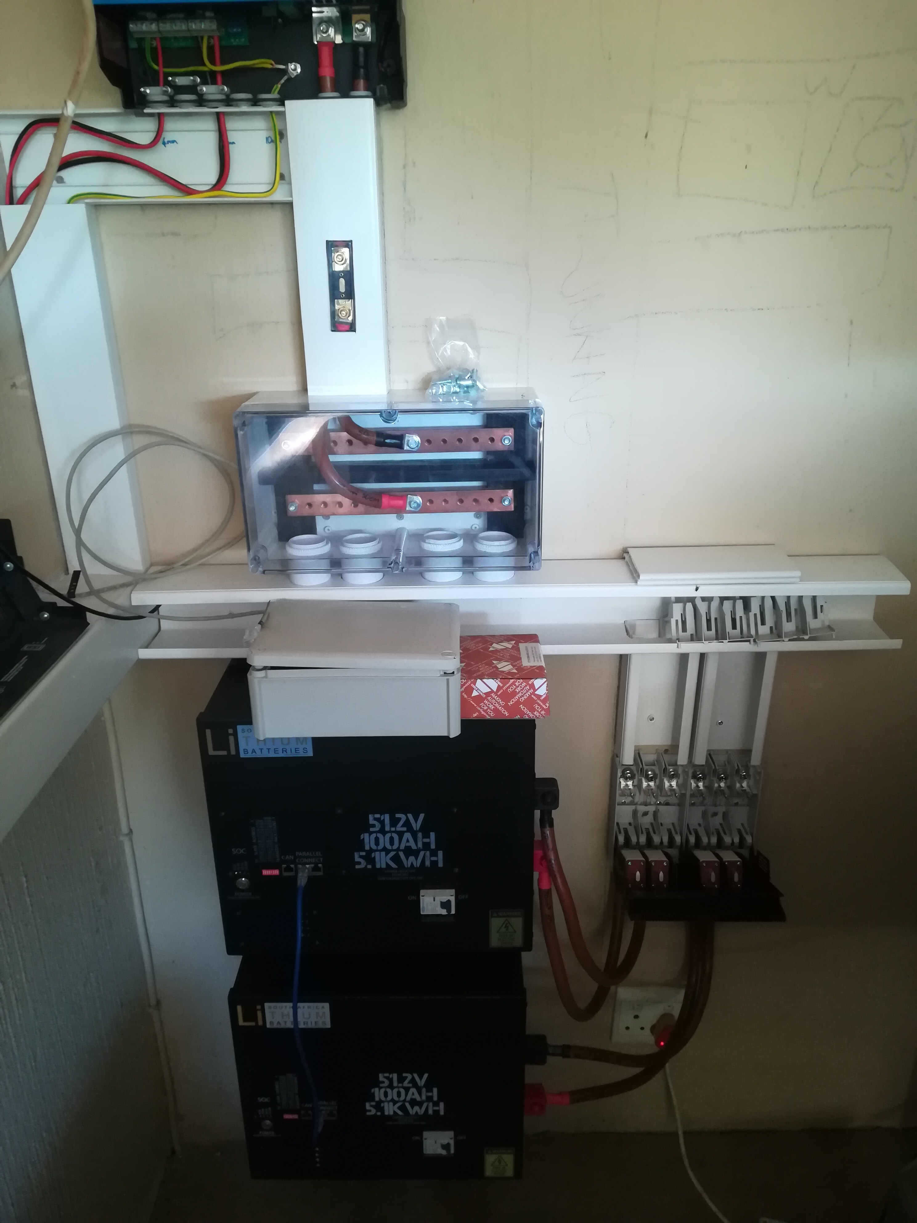
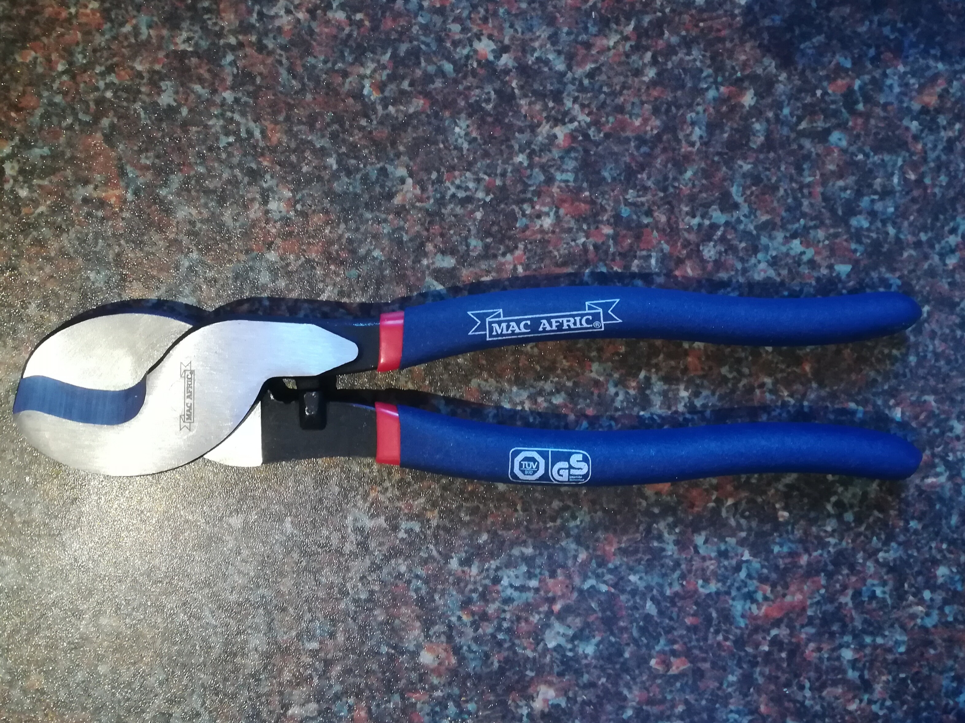
Also for anyone looking for a cheap cable cutter I got this from adendorf for R125 and it cuts the 70mm welding cable quite easily so I’m very chuffed.
I have read through the post to try and see if someone did advice you to keep your DC cabling 100% symmetrical ( I might have missed it). If you dont the one battery will do more work than the other. that is why with Pylontechs and other Lithiums we connect the Positive to the first battery and the negative to the last or vise versa. that is the only way to ensure that the loads gets fed equally from all he batteries.
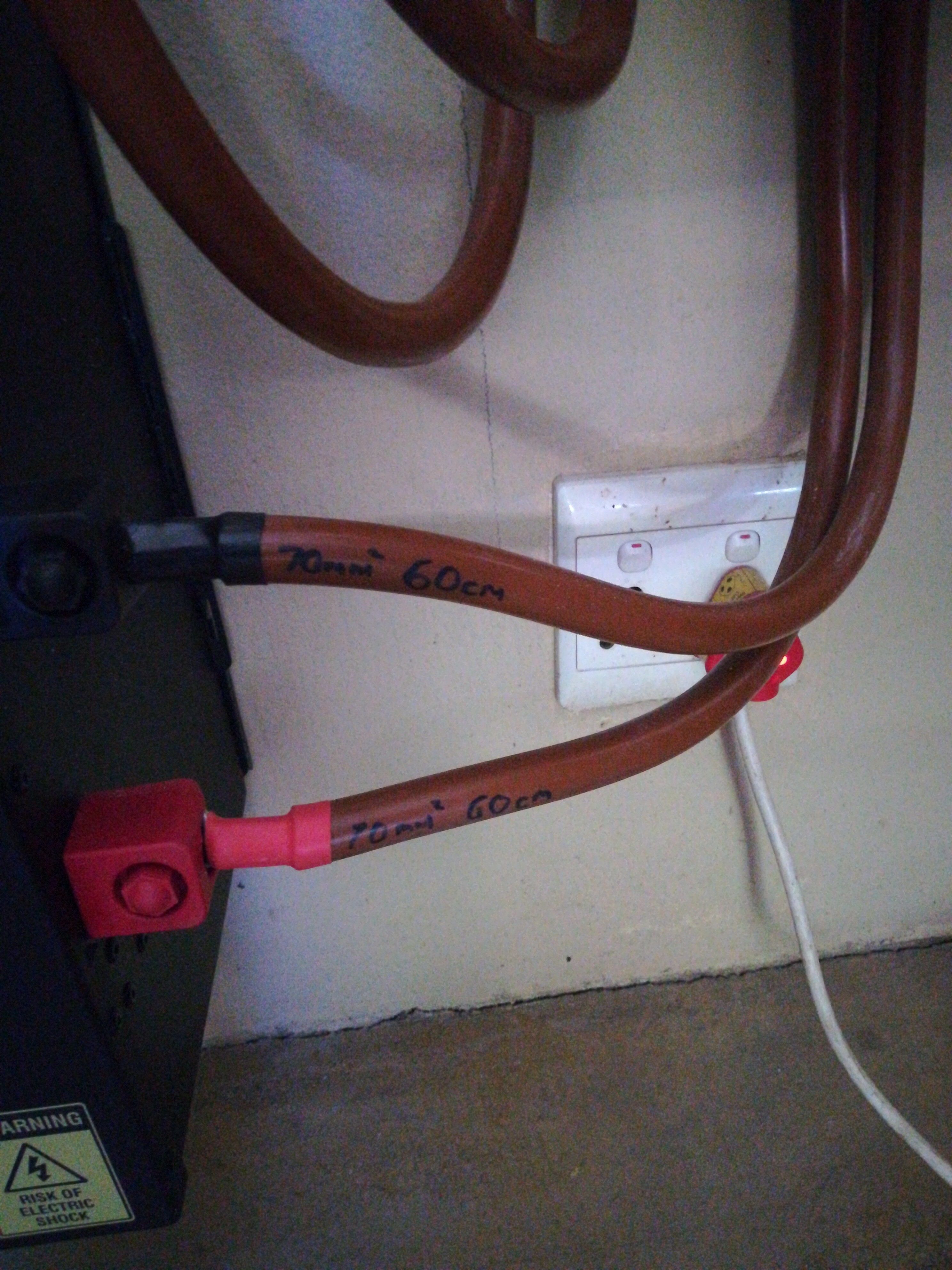
Different length cables in a setup like yours might create unequal charge and discharge over the 2 batteries.
I’m making them 100% symmetrical. Even wrote on cables so if I add battery later I can make up another set of cables the same.
From disconectors to busbar I will also make them the same.
IT’S ALIVE!!!
But I seem to have hit a snag. No matter what I try I cannot get the MK3 usb to connect to my pc it keeps telling me its unavailable and even when downloading driver from Veconfigure3 it still doesn’t want to connect. Any ideas!
At least I managed to update firmware to the latest thanks to @Swartkat and his previous problem he had doing the same.