150ah cells are out, 12 x 100ah 2nd life cells with 4 x 150ah cells in the temporary bank.
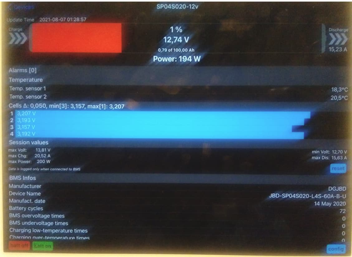
So I thought, let me charge each cell, they came out at 95% SOC, as per BMS.
Then using an EV Peak, I charge them each individually up to 3.65v
Most cells start charging at 3.2amps, a couple at 4.2amps. and they take hours to recharge!
Why!?
So methinks - don’t know HOW I got to this idea, but I did - let’s push the envelope a bit.
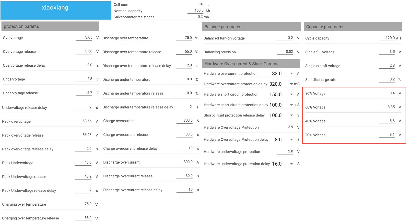
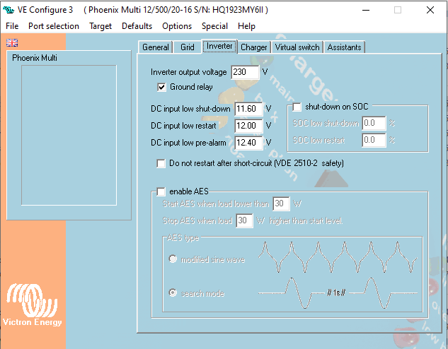
Set inverter like so:

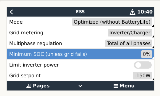
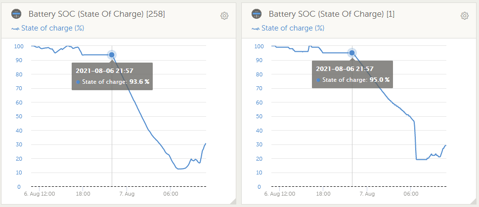
Then I set ESS to this … and I waited …
… and waited …
Keeping an eye on it for HOURS …
… waiting …
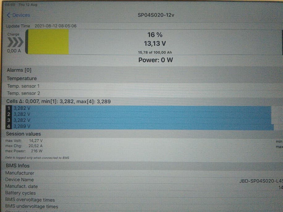
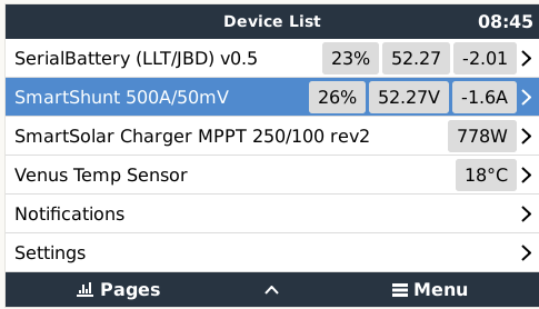
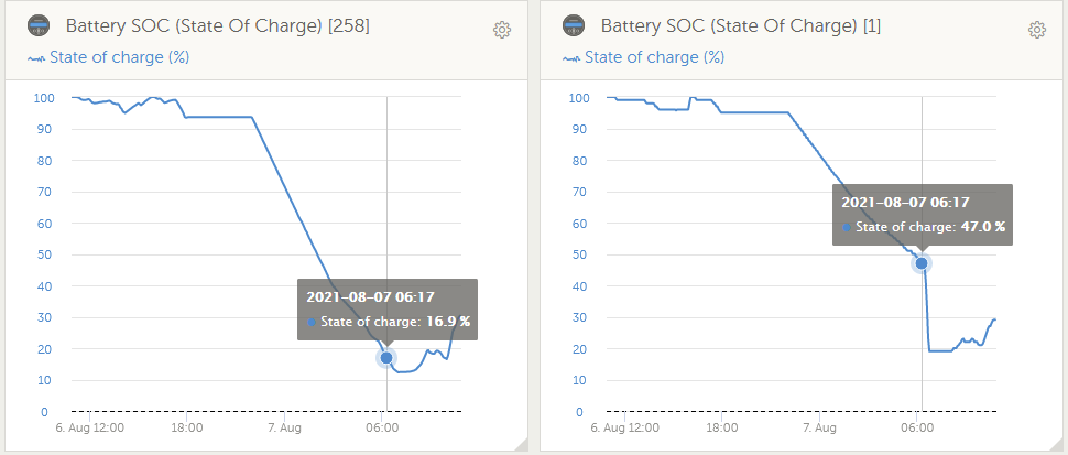
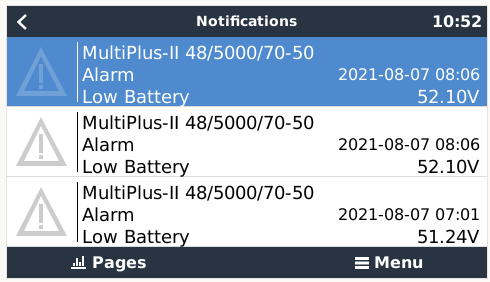
Till it got here:
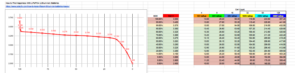
That was on 4 x 150ah cells fully recharged using EV Peak … it took out what I said it could, but nowhere did I dare go to below ±2.9v volts per cell. nope, not is a case of beer see.
Initial Conclusion: BMS SOC’s and shunt is useless out of the box.
I’m so going to follow @Phil.g00 's instructions and calibrate the BMS to the BMV … IF the cell volts behave that is.
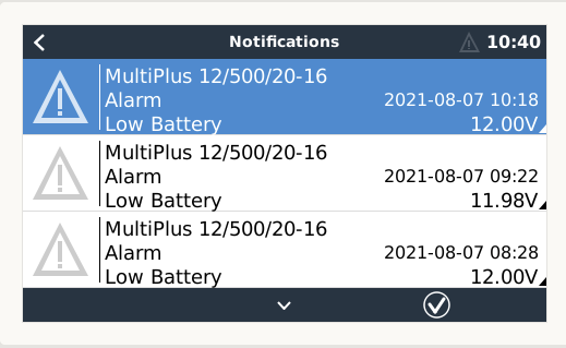
Here is the hold my beer part … I did same on the main system, also set it to 0 SOC …
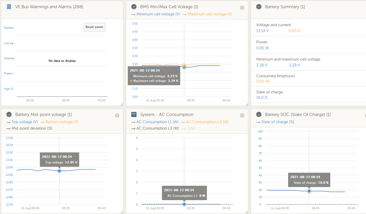
Started here:
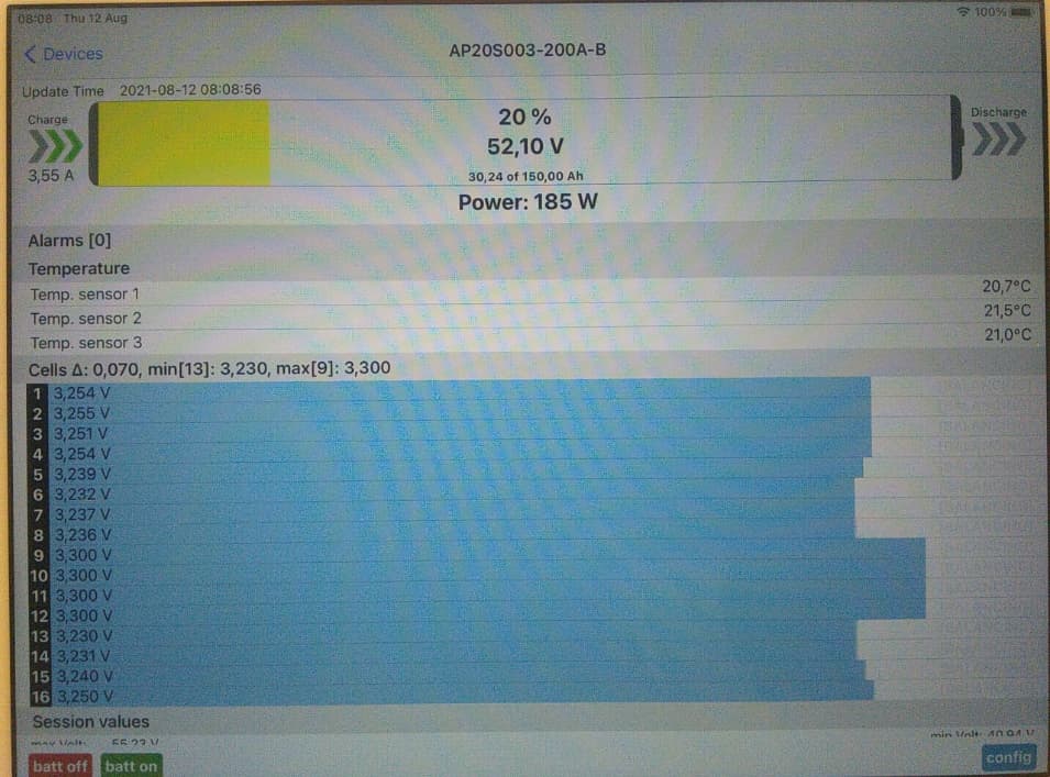
Ended here … bet the 2nd life cells were fine …
But the sun took over …
Conclusion: Do NOT use cells that are not A-Grade, matched A-Grade cells that is.