Help please: Load shedding causing earth leakage trips

Caveat: While I was born with a good dose of common sense and can figure out some electric “stuff”, earth leakage is still beyond my understanding.

Since about a month ago our earth leakage started tripping every time the power comes back on after load shedding and for the life of me I can’t figure out why. Some background/ thoughts:

  1. We have a Goodwe 5048ES, installed about 7 years ago (yes, quite an old model). The earth leakage is on the back-up load side of the inverter. What I don’t understand is how a change in the grid can trip the earth leakage on the back-up load of the inverter.

  2. It only happens after load shedding. If I manually switch off the grid, it works fine. If I switch off the grid during load shedding, wait for load shedding to finish and then switch the grid back on, it’s fine. So it has something to do with load shedding, some instability or spike in grid power. But I don’t understand how this could trip the EL on the back-up side.

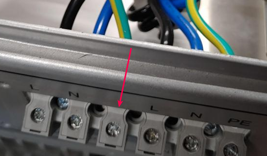
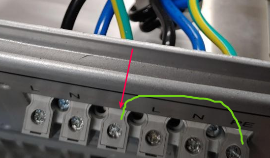
  3. The earth leakage was replaced at the end of last year with an auto-resetting Gewiss unit (GWD4042) which is working great. It test the lines and if it is safe, it turns the EL back on. Except it doesn’t after a load shedding trip. It detects a problem and keeps it off. I manually throw the EL back up, it immediately trips again, and then on second attempt it stays up.

Solutions:
First prize: I need someone REALLY good (Cape Town northern suburbs) to figure this out. In my experience many electricians won’t be able to make heads or tails of the problem.

Second prize: I need to install some thingamajig on the grid feed that waits 30 seconds before connecting the grid to the inverter.

Ultimate prize: Both of the above?

Can someone please recommend a someone (first prize) or something (second prize)?

Thanks!

I installed this for the simple “protection” of the inverter

Once power from the grid comes back - this device keeps it disconnected for up to 4 minutes (it auto senses and configures)

Read about it and give it a try…it also doesn’t cost arm and a leg… :slight_smile:

1 Like

Welcome to my world. Or the world I was in a few years ago (around 2017). I spent (in total) around R8500 to find and fix the problem. The good news is that half of this was metering equipment, which I got to keep, and what man (of our persuasion) doesn’t like a good tool :slight_smile:

The trouble in my case was a combination of things. First, I had a very high standing loss already. Second, I had a number of EMI and/or surge protection devices in my home. And third, the relay test the inverter does before it connects to the grid added enough extra noise to trip the RCD.

So let’s start with standing loss. It is normal for a small amount of current to flow onto your earth wire, sometimes caused by imperfect insulation, sometimes caused by noise and/or surge protection devices. Especially devices with a switch mode power supply – which these days are everything – you could have 2-3mA loss for every appliance. See myself here (in Afrikaans) showing how a coffee machine has a 3mA leakage, which is normal.

Now when you are already close to the edge, like in my case (RCDs start to trip at 15mA, and MUST trip by 30mA), any sort of extra disturbance pushes you over the edge. So in that case, the solution is to split the circuits across two RCDs to lower the standing loss (per RCD) to a lower value. The second time I had this problem (in 2020), that fixed it for me.

Now on to the second item: Noise and Surge protection. These devices add to your standing loss. Your cheap garden variety triangle of MOVs suppression will have nano-amps of leakage, and is usually not the problem, but I’ve seen some multiplug-adapters with built-in suppression (and little neon lamps) that are terrible. Throwing those out (or clipping the fancy plug off and putting on a normal three-point) often solves that issue. Once you have the fancy clamp meter, it gets easy to find these plugs. You can also use an insulation tester, which every electrician should have.

Now for the third item. The inverter. I do not know how the Goodwe handles this, but I assume it does something similar to the Multiplus. Before it connects to the grid, it has to make sure that earth and neutral is correctly bonded on the input, and correctly left unbonded on the output. To test this, it measures the voltage between neutral and earth on both sides, with the bonding relay OPEN. This means that on the output, there is (briefly) around 90-110V between earth and neutral… and this charges all those little capacitors inside your EMI/noise arrestors. Then when the inverter decides it is all good, it closes the bonding relay, causing a very small surge as it brings the voltage down to 0V again. The first time I had this issue, I installed a very expensive transient-resistant RCD, and that solved the issue.

Sooooo… long story short. I would start with an insulation test. Any sparky should be able to do that for you, they all have the meter. Or should have it.

Then I’d look at my standing loss. If that is already very high (over 10mA), split the circuits to get it down to 7mA or so per RCD. This is harder to do. Not every sparky has the fancy meter. A normal clamp meter is not sensitive enough.

Other things to do is to unplug everything and see if you can narrow it down to a specific appliance, or group of appliances, although this is not really possible if you have to wait for load-shedding every time.

Edit: Also! With the Goodwe there is, if I remember, an unmarked earth terminal you have to connect if you want the inverter to properly bond items on the output. I’ll see if I can find the image.

1 Like

Maddening, isn’t it?
Keep trying with your fault finding: Since it only happens when grid power is restored try switching off all CBs on the inverter supply and see if it still trips…

Here ya go.

On the older Goodwe’s, there is terminal here:

goodwe

When the inverter is in island mode (ie the grid is down), it bonds the neutral to this terminal. That means you have to connect an earth wire to this terminal if you want it to work properly.

Please consult the manual and/or your installer, don’t just take my word for it. I’m not an expert on this inverter. I did however see the circuit diagram of the inverter in this picture, and it was definitely the correct way to do it.

3 Likes

I once went down this rabbit hole and rigged up a CT and a scope and I was convinced I will solve this mystery. TLDR: HF components (from the inverter) coupled with capacitance in the wiring results in lowered trip limits, even with all the live wires (breakers) disconnected. The solution is to install an RCD with anti-nuisance tripping, or to split your circuits so that you can have multiple RCDs.

2 Likes

Especially in the modern home, if you have only one RCD for the whole place… just upgrade already. This is the 2020s. Split it up into at least two halves. And use at least “type A” RCDs rather than the cheap type-AC. Type-A in theory is already a little more resistant to tripping, and not as expensive as a type-F or a type-B, or even the anti-nuisance ones.

In his case, he already has a very fancy RCD with an auto-recloser, but the spec sheet seems to say it is a cheap type AC (no mention of auto-reclosing on the GWD4042).

The interesting part here is that the RCD seems to do some kind of line-testing, and then decides not to reclose because there is some kind of fault. That suggests to me a possible issue with bonding, or at least an intermittent issue… which may be no issue at all (the inverter after all has to temporarily disconnect bonding to test the relays). In other words, the recloser might be interacting badly with the inverter relay test. Though I have to say as disclaimer: I’m totally speculating here.

1 Like

Is there a good reason why this is only a problem for him after loadshedding and not when he manually disconnects from the grid?

It probably depends on when exactly that breaker trips. Does it trip immediately when the grid returns, does it trip a few seconds later (as the inverter starts doing a relay test), or a whole minute later (NRS097-2-1 says you can reconnect after monitoring voltage/frequency for 60 seconds)?

Still, splitting over multiple RCDs is likely the cheapest thing to try first. If you have space in the DB, that is.

Edit: In these things, I have learned never to ignore “dumb bad luck” or “Murphy has it in for me”. If the RCD can trip at a more annoying time, it will. When you’re doing the test, you actually want it to trip, so that not-tripping is the more annoying outcome, and the one that will happen :slight_smile:

2 Likes

I had the same issue, and could not figure out why. As @plonkster says, the inverter does not reconnect immediately, the grid input first has to be within spec, and then it has to lock phase again before reconnecting. (as well as the NRS required delays.)

My issue was simple… RCD was faulty - replaced and problem solved :grinning:

1 Like

I see Gewiss sells the recloser as a separate unit too. Eg, the GWD4827P, which sits next to another RCD. Even more expensive than the surge-resistant ABB RCD I installed in my setup.

Looking at the series spec sheet, on page 11, it looks like the recloser is seeing an earth fault. The LEDs on the unit will supposedly tell you where it gave up. If there is a real earth fault, it is probably of the borderline kind, as mentioned.

I had the same problem at the same time as Plonskter.

In our case, the earthing of the house has been faulty since the day it was built, The problem was in the box in the street.

Now have a TNC-S connection. Problem sorted.

This could be an issue. I had a look and there is no cable going to this terminal. I’m not an expert, I don’t have a manual and the installer emigrated several years ago. Who/ how can I double check this?

Note: The earth cable from the back-up connection is however connected the earth cable from the grid (bonded to neutral before the inverter) that also goes to the DB.

I actually have the GWD0978:

Easiest way to check it, is to measure the voltage between neutral and earth while the grid is disconnected. You want to see a voltage very close to 0V. If it is not bonded, you will typically see 90V or so (in my experience, it will vary, but it will be close to half the grid voltage).

The recloser might be objecting to that unbonded neutral.

In the picture I posted, you can clearly see an earth wire on the inside of the inverter. If it looks exactly like in the picture, I’m sure you can just go ahead and earth it. Do we have any Goodwe people around, or anyone who has installed one? @JacoDeJongh ?

1 Like

I can gladly try and assist, but I don’t think Niel trust my opinion, I have tried to explain all the above to him in a private conversation two weeks back and had a gap to go to his site on a specific Saturday. I got the impression he felt that my experience with these problems was not correct. I did plan to help him on my last day in Capetown but we left site at about 5pm and I still had to drive to Prince Albert.

Sadly I could not get to his site.

The new ones still look and work like that.

1 Like

Well then it is an easy improvement. Just tie these two together.

goodwe

Note, I called it an improvement, not a fix. It might fix the recloser. It does not fix the nuisance tripping.

Back in the day I briefly considered a recloser too. But in the end I dropped that idea. I want the power to stay on. I don’t want it to trip, and then return in 10 seconds. Sure, 10 seconds is better than never, but if I am going to spend big moolah on it, then I want it fixed, not patched.

So after doing this, you may find that you will still have to find the leak, and/or split circuits.

Further to that, if I am spending on the other side of 5k on this, I’m moving everything to RCBOs. Then every circuit has its own combined over-current/earth-fault protection, and only the culprit trips. RCBOs start at around R500, R800-ish for a Schneider, R1500 for ABB. Gets expensive real quick, but I doubt you have that many circuits on the output of the inverter anyway.

1 Like