I decided to do this and standardized on a 20A RCBO for each plug circuit. I found an 18mm version so it fits in a what was a single MCB spacing. 36mm versions can be found cheaper, but who catered for doubling the size of their DB in a retrofit?
So if I understand this correctly (and if SANS allows) you can use these breakers instead of an RCD on your whole board (or split) combined with a normal overcurrent breakers? If would be really cool as an earth fault would only trip the circuit with the earth fault (if I understand correctly). Would help a LOT with finding issues…
I don’t know the letter of the law.
I’d have thought the minimum required protection functions are defined in SANS.
If whoever signs the COC off has proven that the defined protection functions indeed function as specified by the SANS.
I’d argue SABS approval be damned if I exceed the minimum protection standards.
My understanding from a long time friend and former colleague who now does COC sign-offs in ZA, is that he has that discretion.
Yes. You can split the board. An RCBO then doesn’t have an RCD preceding it. A normal MCB must have an RCD in front of it.
But SANS might be a legitimate question here. RCDs disconnect both live and neutral. Some single-space RCBOs only disconnect live, so an earth-fault on neutral remains in the larger circuit.
So perhaps I was way too fast with that suggestion.
Apologies for spamming this a bit, but I think I’m still on-topic… mostly. Just carefully consider the contact arrangement.
This looks like a good option. Or something from this family. It is 1P+N, which means it has overcurrent protection only on the live terminal, but it does switch both lines. And it fits in a single DIN space. So it provides all the protection of a normal RCD (which doesn’t have over-current anyway), as well as overcurrent (which is already only on live in a normal installation). I can see no problem here.
The version I have bought is 1P+N as well, but if I recall 20A overload is the rating that is the most universal allowable fit for plugs and mixed circuits (as specified by SANS) on 2.5mm2 cable.
( Again I can’t blindly quote ZA rules and regs, but for some reason, I made this mental note).
So I switched the grid off and measured 30V between earth and neutral. I then bridged the two earth terminals on the Goodwe (as in your sketch) and measured 12V (after switching the grid on and off again). It’s not quite zero and not quite 90V so I’m not sure what to make of that.
(I quickly opened up the Goodwe and there is an earth wire like in your picture.)
If we remain on stage 2 we won’t have load shedding until Sunday or later so I’ll have to wait and see if this solves the problem, but I’m happy to take to more advice.
Sjo, I don’t think this is fair Jaco. This specific Saturday I wasn’t home (and in fact had very poor cell reception) and phoned you as soon as I could. I never questioned your experience or expertise. In fact I said I don’t trust a regular electrician with this complicated issue and need someone with your experience. The reason I’m here on the forum is to find someone with your experience in Cape Town who can assist.
If I questioned your advice, it was simply to understand and I apologise if I came across as distrusting. I am simply curious, have only a very basic understanding of AC electrical systems (and really don’t understand EL), and maybe take a bit long to get my head around things.
@plonkster I know there’s many different types of earthing. It seems like there’s still a floating N present even after the bridge, surely that means that the E that was bridged isn’t a proper reference to earth? Would this type of thing be possible if the earthing wire of the house has an issue?
It should have been zero. When the inverter is running islanded, that unmarked earth terminal is connected to the neutral. The voltage between the output neutral (not the input one) and earth should be zero if this works correctly.
Good point. Measure between earth and neutral on the input side, while the grid is ON. That should also be zero (or very close to zero) if it is bonded correctly.
There are different earthing systems indeed, but in South Africa our houses are all TN (Terra-Neutral), either TN-C-S or TN-S. The difference doesn’t matter to the home owner
I spoke to Niel over the phone last night (we know each other very well) and he told me he has an earth spike, doesn’t get earth from municipality. So I also told him to test N to E with the grid on.
Possibly (but not really sure how likely) the earth spike could also have become “insulated” from earth and now has a too high resistance and the wire through the house is fine. Presumably you need specialised equipment to test resistance to earth?
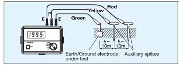
This shouldn’t really cause nuisance tripping. It would rather cause the opposite (not tripping when it should). Yes, you need a special tool with three spikes. They go for around 4k… even second-hand.
Yeah not for the nuisance tripping, but for sorting out the floating neutral? Hopefully, sorting out the floating neutral will have the RCD automatically re-engage and at least things like fridges wouldn’t stay off while no one is home.
But that should not affect the bonding. If I tie neutral and earth together with a copper wire, it doesn’t matter that this combined connection is poorly connected to earth, a measurement (on my side) between T and N should yield close to 0V. They are physically connected together somewhere in the system.
In this inverter application, there is a relay inside the inverter that bonds T and N while it is operating islanded, and un-bonds it when it is connected to the grid (because the grid is already bonded, and you should only have one bond at a time).
Anything higher than zero, would be solely the voltage drop over the (current carrying) neutral conductor, and must be less than 5% of the line voltage at full load.
No, but also yes. Many newer developments use TN-S. There is one good earth spike at the transformer, and all the houses in the area are earthed to that spike. The earth and neutral is also bonded at the transformer. You have no spike on your premises.
But in many older neighbourhoods, or small towns, you still have TN-C-S. Two wires from the transformer (neutral and earth is one combined conductor), and then you put in an earth spike on the premises, bond it again, and then you have a separate earth from there onwards.
But I’m pretty sure none of this is causing the nuisance tripping. Go ahead, and sort if out… but I think it is a red herring in the current debate.
I really don’t know the codes for earthing systems, but I noticed on the spec sheet of his automatic reclosing device it lists “TT - TN-S” under distribution systems.
Does he not have a TN-C-S in which case it isn’t covered by the device’s spec? Not sure how that could be a problem…
But yes, sorting out the nuisance tripping is first prize…