The standard 3kW element isn’t ideal for most RE installations due to the heavy load.
So there’s a move to lower power elements.
The 4x4 Community forum has a thread suggesting the use of a SCR controller to reduce the power to the existing element rather than replacing it: Geyser element controller
It seems like a good idea at first but I would be hesitant to introduce this kind of non linear load onto an inverter.
If you have a grid-tied system, most people just won’t care about that. You are not billed for apparent power (aka peak current), and there are no penalties for poor power quality.
Similarly, if your inverter is capable of carrying the full power, in other words it can handle that peak current and the only reason you’re “dimming” the geyser is to prevent large discharge currents on the battery, it should also be perfectly fine.
But in both these cases you can make a case for at least switching whole cycles, not like a cheap SCR dimmer that chops the leading face of the sine wave.
The one place this breaks down is where the inverter is smaller. For example, if you’re running a 24V 3kVA Axpert, and you want to power your 3kW geyser element through some power-reduction device. Then the cheap SCR method is not going to do that poor inverter any favours. Then it’d be better to go to a smaller element or a dual-element.
Even with the 5kVA Axpert, I have a feeling that it’s going to hate you at certain power ratios. Eg at 50%. That’s basically switching the element on right on the peak of every sine wave. The success of this endeavour likely depends also on staying under 40% or so. I thumbsucked that number… don’t ask me to prove it.
Let me give you another example, from the blue stable. If you put a hairdryer on one of the smaller inverters, one that can just barely handle the device, and you put it on half-heat (which basically puts a diode into the circuit and lets through only half of the sine wave), the inverter will switch off. It doesn’t like that. Run that same hairdryer on a 3kVA, and it sounds a bit different, but it handles it fine.
1 Like
Ja-nee!
I think there are good engineering practices that should be followed.
Generating harmonics wastes power. Any electrical engineer will endeavour to minimise these since it’s wasted power and being efficient, especially in this business, makes sense.
Some engineer will realise that we simply need an geyser element with 5(or 4? been a while since replacing one) contact points like we have with the solid stove plates. Depending on which point you connect it changes the amount of power it draws. Then you can easily draw 1KW, 2KW, 3KW or 4KW depending on where the current is connected. There is a need in the market, I wonder how long it will take for the idea to be built.
2 Likes
Bath/sink immersion elements are practically standard in Ireland.
These are 2 separate elements of different wattages. If you want to be creative series and parallel connections will provide another 2 power selections.
3kW 3 phase (so 6 terminal) elements are also available with a bit of googling.
These could be wired for single phase.
2 Likes
Voltex used to make a dual element. I cannot find it anymore.
Google digs up an article from News24 that points to a company called Energi Mart (sp), which is apparently a stones-throw from me, but they too seems to no longer exist.
I think I’ve seen one guy modify the mounting plate and add his own.
Soooo… not much in the way of options down South.
I never knew those existed found one locally with 3/4.5/6/9/12KW, but the rating is too much. I understand why, the whole idea is to quickly heat water by supplying a lot of power.
What we need is a 0.6/1.2/1.8/2.4/3.0 KW element with a temp sensor and Wifi controller and with mqtt integration. Is that too much to ask?
1 Like
How you wire or switch the 3 elements is your choice:
For example, take a 4.5kW element it has 3 x 1500W elements:
1 element only = 1500W
2 elements in parallel = 3000W
3 elements in series = 500W
2 elements in series = 750W
2 in Parallel with 1 in series =1000W
1 in parallel with 2 in series = 2250W
1 Like
Mmmh this sounds excellent.
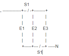
L ----------------+-------+
                  |       |
                   \ S1   \ S2
                  |       |
                 E1      E2
                  |       |
                  |       +--------+
                  |       |        |
                  |      E3        \ S3
                  |       |        |
                  |       +--------
                  |       |
N ----------------+-------+
Only S2 closed: 750W
Only S1 closed: 1500W
S1 and S2 closed, S3 open: 2250W
S1, S2, and S3 closed: 3000W
3 Likes
You guys must be coders…
You’ve been spoiled at the ability to edit a parameter and change the design ![]()
It is less effort than breaking out the entire tool (which I use so infrequently that I have forgotten how), or drawing it on paper and taking a photo… sorry ![]()
I’m not referring to the drawing. What happened to the engineers with slide rules that designed a plant and got it built as per design and then commissioned it??
I suspect most of them are retired…
There is a new season of “Space Force” on Netflix. A Slide rule features in one of the episodes.
This should spoil people for choice.
Personally, in 30 years I have only ever used the “defrost” or the “nuke” setting on the microwave.
S1 open = 3 elements in series (500W)
S1 closed = 3 elements in parallel (4500W)
1 Like
I reckon that a PWM current controller might be a good tool to determine what is the optimal element size you require…
Thanks to @_a_a_a we have this neat linear AC current controller:PWM Based AC Power Control using MOSFET / IGBT
2 Likes
99% of the time you use “nuke”. But for the last 20 years or so we’ve had an auto-reheat feature, as well as a “fresh vegetables” option. Man, that is nice. I also have a recipe for “krummelpap” that requires 10 minutes at medium.
This discussion reminds me of a book I read around the same time ago, written by Alan Cooper. In that book, he argues that the simplest (and correct) interface for a microwave is a round button to vaguely adjust the time (since nobody needs exactly 27 seconds), and one to open the door.
Round about the time I had kids, and it took 17 seconds to correctly reheat two tablespoons of pumpkin… I realised how wrong he was… ![]()
Edit: Every baby book declared that one should not heat formula milk in a microwave due to the danger of scalding. By the third month, we knew exactly how many seconds an “ounce” of liquid required… and besides, you test it on your hand anyway.
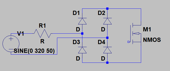
I have previously used a circuit like this to control the current through a heater element:
V1 is the AC source (this program still shows it with a + and -)
R1 is the element
You can PWM the MOSFET (or even just use a switch if you like) to control the current through the element.
With a bit of filtering you can even have a very nice looking current at any level you want just by adjusting the duty cycle.
1 Like
I think this circuit has shown up elsewhere on this forum too. Essentially it’s a rectifier. You allow AC current to flow through the rectifier by “shorting” the DC side.
Of course we’re talking about 4 diodes with a 0.6V to 0.7V drop (assuming standard silicon diodes), at as much as 14A, so you’re looking at 10W dissipation per diode (times 4) if you run 100% through this. So if it was me, I’d probably limit it to something low-ish, and put a switch across the device for “boost mode”.
Almost correct. Since only 2 diodes conduct at a time, you get times 2. Or rather half the dissipation per diode times 4. Still going to be about 20W at full power, but as you said for full power you can just use a switch to bypass it.
1 Like
Gaaaah! Right you are! ![]()