Is that not the Delta - the difference between min/max cell?
If it is published, use that.
That is coming I’m led to believe, showing all cell values on the Venus.
This midpoint thing is wasting time with the above info available.
Is that not the Delta - the difference between min/max cell?
If it is published, use that.
That is coming I’m led to believe, showing all cell values on the Venus.
This midpoint thing is wasting time with the above info available.
I think the deviance as implemented now is a percentage value, saying how far to the left or right that midpoint is. It is not a statistical value. I am proposing using it in the place of the normal deviation value… which is a tiny bit naughty, but closer to the original intent.
The SD tells you if the cells are spaced closely together, or far apart. Together with the mean (which is easy, pack voltage divided by series cell count), you then know whether the pack is leaning towards a low cell count, or a high cell count.
All of this is speculation. I’m thinking about stats that would actually be useful… ![]()
In an LFP battery, there is always one cell that shoots out a bit when it is 100% full, so there is always going to be a midpoint deviation at 100% SOC.
I’m not aware of such a movement. Besides, in really really large batteries, it becomes almost unmanageable. In container-sized batteries (and we have a couple of those), this could be hundreds of values. But a statistical approach, knowing whether we are predominantly low or high, and in what module the low/high cells are, that should be ample information.
We don’t own container-sized batteries, nor will the driver Louis has written, help much there either. ![]()
I see a value like Delta 0.008v, doing the sums, direct from the BMS, in the App software…
Even a % will work.
My point is, Midpoint is a tough calc, or workarounds, I simply cannot understand why bringing lead-acid thinking to Lithium banks.
Anycase, I said my piece, as I’m quite “qualified” on THIS matter, to have a strong opinion, if I may say so myself.
Line 50 … not in yet, I was told it is coming, the start of that has been built in already.
+1, and then it should perhaps be just removed from the code or at least be disabled by default.
I do not like to have a feature that clearly does not do what it originally was supposed to do …
Showing wrong values is not a good thing.
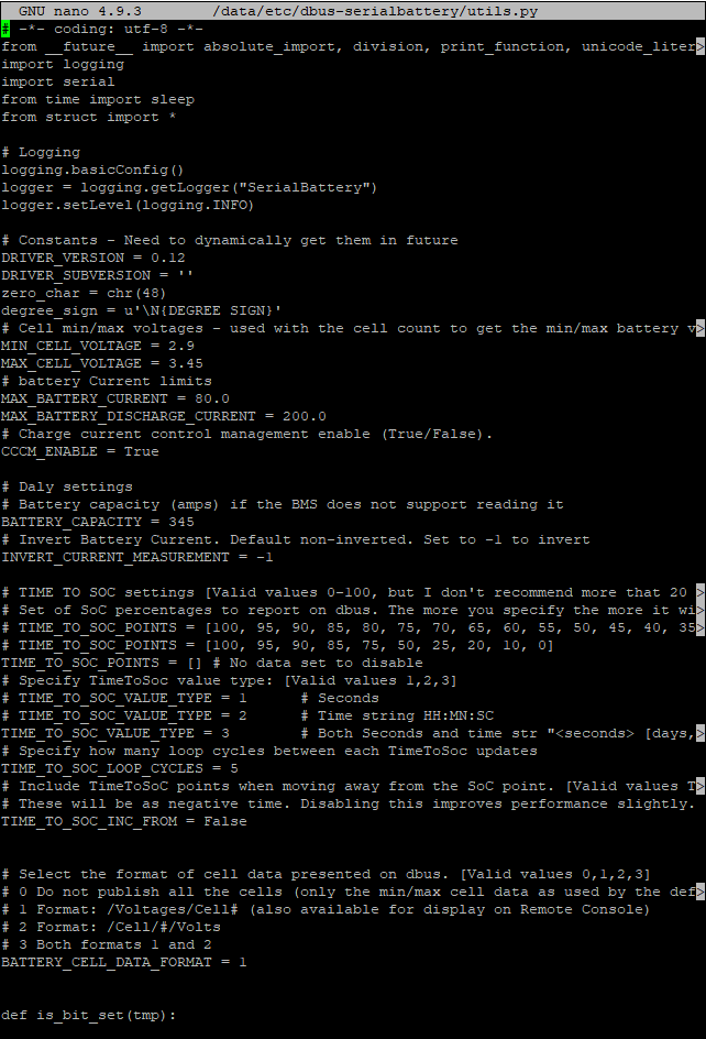
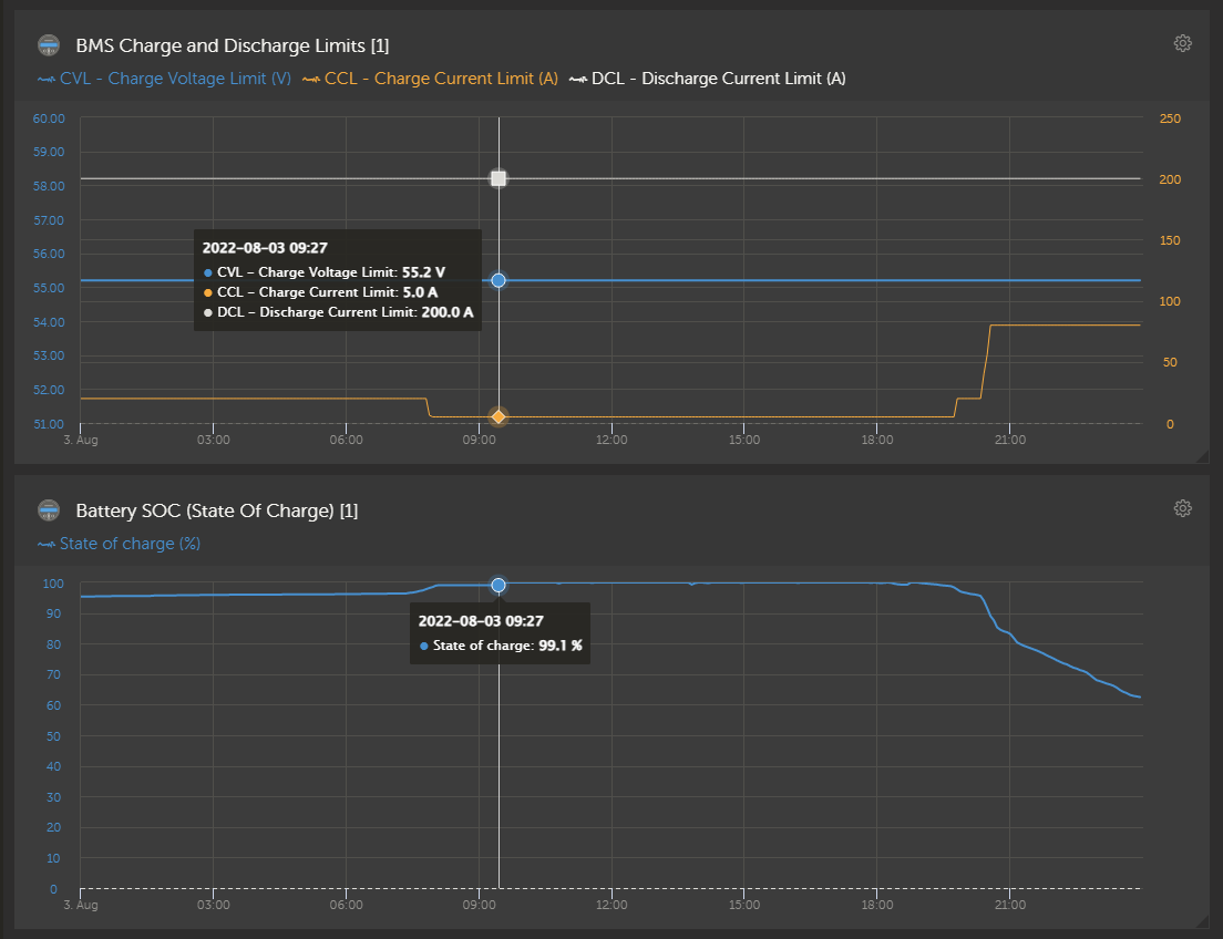
In your VRM advance section take a picture of your last full day of BMS charge/discharge limits graph and Battery SOC graph
That is working perfect.
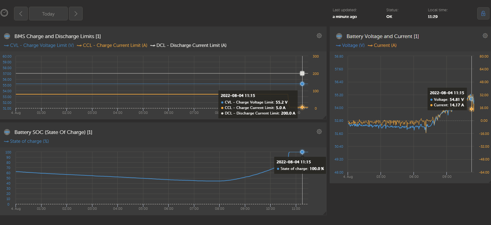
When the SOC is at 100% the current limit is 5A and when the SOC goes down the charge current increase.
Well you mean it fluctuates 100 to 98 and back, if so, then wil be more better to set for high current chagers like
0-85% - 100%
86-90 - 1/2
91-95 - 1/4
96 - 98 - 1/8
99-100 - 5A
    # Change depending on the SOC values
    if self.soc is None:
        # Prevent serialbattery from terminating on error
        return False

    if self.soc > 99:
        self.control_allow_charge = False
    else:
        self.control_allow_charge = True
    # Change depending on the SOC values
    if 98 < self.soc <= 100:
        self.control_charge_current = 5
    elif 96 < self.soc <= 97:
        self.control_charge_current = self.max_battery_current/8
    elif 91 < self.soc <= 95:
        self.control_charge_current = self.max_battery_current/4
    elif 86 < self.soc <= 90:
        self.control_charge_current = self.max_battery_current/2
    else:
        self.control_charge_current = self.max_battery_current
The midpoint graph is now disabled by default. You need to enable it if you want it.
Based on the discussion above and my post before around 10 days, this is some useful piece of information to be collected and displayed/published by the driver:
Probably my wrong impression this is easy for implementation comes from the fact that if this is available in the BMS does not mean they are (or can be) published to dbus. @Louisvdw will advise whether those points are feasible for implementation.
That is the real issue. The driver publish everything that the dbus can accept. If you look at the combined features of all the official batteries the driver just about does everything (if the value is available in the BMS or we can calculate it)
The problem comes in when we want to see data that does not have a place in the Venus GX dbus system and we try to reuse some pieces for what they were not meant to do.
So those would be disabled by default and people can activate it if they want it.
It would be nice if toggle all the settings in a UI, but we don’t have that (yet).
cant undestand
This might be a little bit OT, but I am thinking to integrate a function into the driver code if possible …
I am using capacitive balancers on all my batteries. They work just OK for me. These boards have integrated voltage thresholds at which the device is enabled/disabled. But these threshold are fixed and the function is not intelligent as it does not differentiate bewtween charging and discharging.
My question is, if it is possible to switch one of the integrated relays of the GX devices from the code. If yes, then it would be possible to integrate a more intelligent switching of the balancers depending on cell voltages and also differences as well as the charge state. All this information is already available in the driver.
BR, Jörg.
I would like to ask all of you what is your experience with the different BMS types and vendors from the supported list, and most specifically how they cope with small current measurement (<300mA)?
I am especially interested in 16S packs because it is highly possible those systems to have idle current bellow the mentioned value.
Here is my experience with JBD SP25S003-16S, 100A (till now). It can be said its amp readings are accurate, but it does not show current values (charge/discharge) bellow 400mA. Even after calibration of the idle current value, it starts showing amps once the reading is more than 400mA. When the inverter is in idle (MPII 48/3000) the BMS does not count this at all.The inverter idle consumption is around 250mA (together with the 1W consumption of the electronic el.meter connected to the output).
I tested this once for a whole night (running the inverter at idle) and the SOC was the same in the morning, meaning that the BMS not only does not show the low current, it does not measure and count it at all. This will no doubt lead to a SOC drift over time, especially it the pack is operated in the range 20-90%. I believe the BMS should perform some SOC corrections (I think I saw such thing while initial charging the cells “on the bench”, but do not know how and when it decides to perform this and suppose this is done when the pack reaches full or near empty.
What are others observations on this issue for different models and types of BMSs?
You will see the same on most BMS. The level of accuracy will just be different for each one.
When you measure current flow with a shunt, the shunt will show a voltage drop over it, which the BMS must measure. The finer that measurement can be the smaller the increments of measurement. The smallest increment would give you the minimum value that it can read.
So for a 100A BMS the shunt would use something like a 125A/50mV. That means when there is a 50mV voltage drop over the shunt it would indicate that 125A is passing through. Or 2.5A for each 1mV measured.
To be able to measure 400mA, your BMS can measure up to 0.16mV (or 0.00016V) differences if using the shunt as in my example. Shunts are normally made in 50mV, 75mV or 100mV models with 50mV giving you less accuracy at a cheaper cost and 100mV the most accurate at a much higher cost.
Unfortunately manufacturers don’t normally tell you which model shunt they used, but if you buy the cheapest BMS on the market you should not expect the most expensive components inside.
For instance the SmartShunt is more expensive, but also more accurate and can measre up to 100mAh compared to the 400mA of your JBD BMS.
That does not mean you now have to go and buy a Smartshunt to get the 400mA down to 100mA. The BMS has a few tricks to solve this. It knows about the voltage of each cell (something a seperate shunt can not know) and it can use that to adjust the SOC value if too much drift has happend.
In the JBD BMS app you will see there are cell voltage settings. These are the triggers to recalc the SOC if the cells reach those voltages and the SOC is not inside those limits.
I would not worry to much about those small current measurements. They have a small impact compared to the larger currents you will normally see, and the rest of your system also do not have that accuracy. In my tests the chargers in the MPPT and the Mulitplus also cannot measure below 500mA-800mA.
I have just checked with my 100A JK BMS JK-BD6A20S-10P.
After calibrating the current at 15A (using a power supply with calibrated current reading), I see a 0,4A offset around the zero point ( 1A real current is displayed as 0,6A) and roughly 0,2A resolution (measuring value jumps from 0,2A to 0,4A to 0,6A when the current changes slowly).
This is really bad! And the offset is even worse than the ‘deadzone’ around zero. It gives 0.4A error on all small currents flowing.
It seems that an offset calibration is not possible with the JK BMS. At least not via the Android app.
The 0,2A steps show that they are possibly only using a 10 bit ADC. This is extremely low when 12 bit or even 16 bit ADCs are available for just a few $ and 12 bit ADCs are already integrated in a number of microcontrollers.
One sugestion on actual case. I had 3 batts and ones cell blow, second i reinitialise by top balaning and in system was only onr battrry with soft cells. In evening i git error 38 on mppts batt disconected. Luckly no PV power no charger spike so mppts only switch off i hope will test tomorow. Can bms report switch off discharge to warn mppts to stand by ?