I have a cerbo cx with a bms jbd and the driver working for months without problems but yesterday I saw that there was an update for the venus and by mistake I gave it update thinking that I would still get a confirmation screen. It turned out to be a beta version, 2.85. Soon after, I lost communication with the em-111 counter and also had problems with the bms. I did many tests and went down to version 2.84 and 2.80 but it was still the same. From what I could see it seems that when connecting both the bms and the counter to the usb ports it recognizes them but always in usb0 so only one works. Delete the driver that was version 0.9 and download the venus to 2.72, then install the 0.10 driver but the problem continued, as I read that with version 2.73 it did work and I finally recognized the two usb in their correct positions .
I think this problem is known by the community, it took me all day yesterday of tests, now I don’t know if the venus 2.84 can be installed with the driver v0.10 or it won’t fail again.
Thanks for the detailed feedback.
Yes there is an issue where the driver incorrectly identifies the power meters as BMS in the 2.80+ venus firmware.
For now the fix is to stay on V2.73 until it has been fixed.
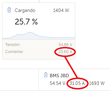
Between the bms jbd and the bmv-702 there is a very important difference in current reading, not so much in voltage. I think it can be adjusted with jbd software but I don’t know how to use it. Have you seen these differences in your teams?
I would expect differences, but it should be much smaller.
Do you have anything else connected on the BMS before the BMV?
So, I got tired of waiting @Louisvdw . What did you expect!? ![]()
v2.84 with LS and the Carlo is gone, as expected.
So I thought a bit, took a chance, and ran this command: sh /data/etc/dbus-serialbattery/disabledriver.sh
Rebooted the Cerbo.
And the Carlo came back online.
Maybe that is an idea to automate until the issue has been identified?
Bugger, now I have this … every few minutes. Geez, I never get it easy. ![]()
The same thing happened to me until I went back to 2.73
In the end I learned to calibrate the jbd with the software. It has a button to calibrate the 0mA that we have to press when we do not have current flow, then the same for when it is charging and discharging but in this case we have a box where we must put the value that we want to set and it is a little more complicated if it is continuously varying but in the end it is achieved
My programming knowledge is limited, if not null, so forgive the question, could a driver for outback power be made without much complication starting from your driver and this other project?
I’m riding it out … seems more stable now. The last resort is to go back to 2.73.
yes we could use that code (GPL license) and add the Outback to the serial battery driver. It is just a matter of time and if there is enough intrest from users to add the Outbacks.
Well, let’s see if there are more people interested, I’ll help what I can with the tests, but for programming I stayed in Pascal
I give up … back to 2.73 with Level 4 LS.
Even data being sent is drama, see the Blue:
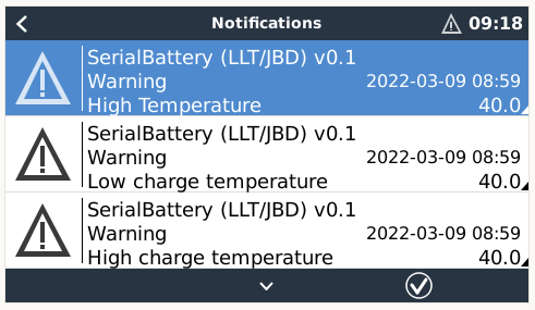
Every few hours I see these “warnings”.
Forgive my ignorance, what is level 4 LS? Why don’t you mean venus os large, right?
On the other hand, has anyone tried the 2.72 large? it works?
Yes, it does work IF you want to use like NodeRED as one example. BUT, I don’t like it cause each time there is a Venus OS release, you have to do the update manually.
UPDATE:
I have uninstalled Louis driver for now.
Want to see how it all works without the driver as I have a BMV for the SOC.
BMS vs BMV SOC is close as damn on a balanced bank. The BMV is more accurate ito coulomb counting methinks. BMV is more accurate adding the cell voltages to the equation.
But on a balanced bank, it should be close as damn.
Hello @Louisvdw.
There is a part in your code in def read_serial_data, could you tell me the meaning of if start == 0x4E57 and end == 0x68?
if start == 0x4E57 and end == 0x68 and s == crc_lo:
return data[10:length-19]
Hi @Cristian
I am assuming you are talking about the JKBMS’s data read.
MODBUS works with data frames which is a set of bytes that is structured in a way to transfer the data. Each frame has a start and end indicator and for the JKBMS the start is 2 bytes (in hex 4E and 57) and the end is 1 byte (in hex 68).
So this bit of code if checking that we received a valid response from the JKBMS. This along with the CRC will show us that valid data has been received which we can then use.