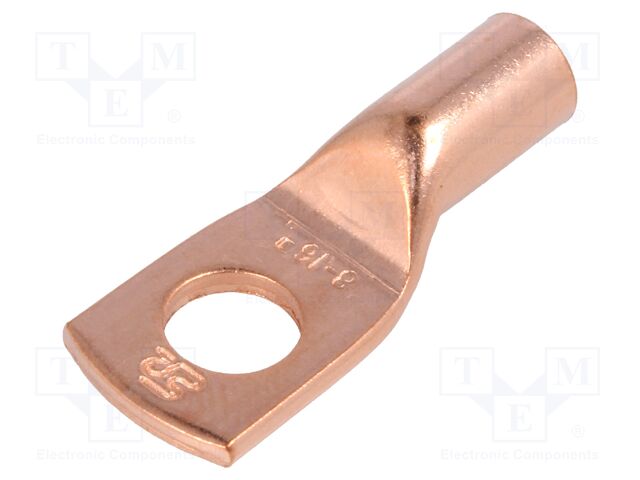
@Louisvdw, how is it advised to have those stock wires terminated (on JBD SP25S003-16S, 100A (seems the same like the Overkill solar 16s version)?
Can I use standard crimp lugs (16mm2) like those or the BMS wire tips must be soldered either to a open-crimp lugs like those or soldered to a piece of copper bus?
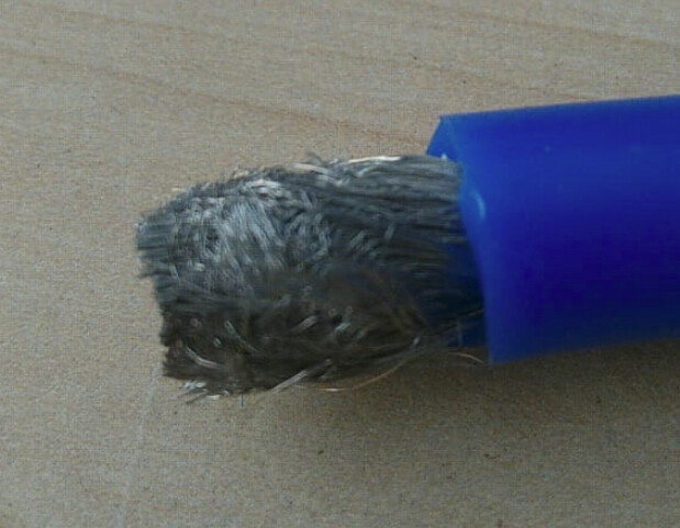
I was told that BMS wires should be soldered, not crimped. I do not know whether this advise is related to the particular wires type of the BMS (very large amount of very thin wires), which differ from the typical copper cables wires used for the connection to the inverter (let’s say this way) and for the jump cables.
Crimping is an excellent way of terminating wiring. However you need to have the exact lug size and its crimping tool. Any old crimped lug is not ok. (And believe me I have an array of crimping tools and still find it a a challenge!)
So it’s safer to solder lugs onto the wires.
Ensure you have the correct lug/terminal for your needs.
Thanks for your answer. The stock wires of JBD SP25S003-16S, 100A are 2x10AWG (2x6mm2) and the closest size lug is 16mm2 which is a little larger than the 12mm2 (2x6mm2) BMS pigtail.
Anyone who is using the same BMS share his experience.
I will never ever solder when I can crimp lugs. The debates on that over the web gets intense, but I have never seen a lug melt, but I have seen solder running out of a lug due to a battery fault.
The very fine wires in some very flexible cable, yeah, to get a lug on them is quite a challenge!
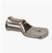
Use bell-mouthed lugs, it makes life easier.
I found they are difficult to get hold of in ZA, so I bought a copper pipe swaging tool which I hope will be able to produce bell-mouth lugs from normal lugs.
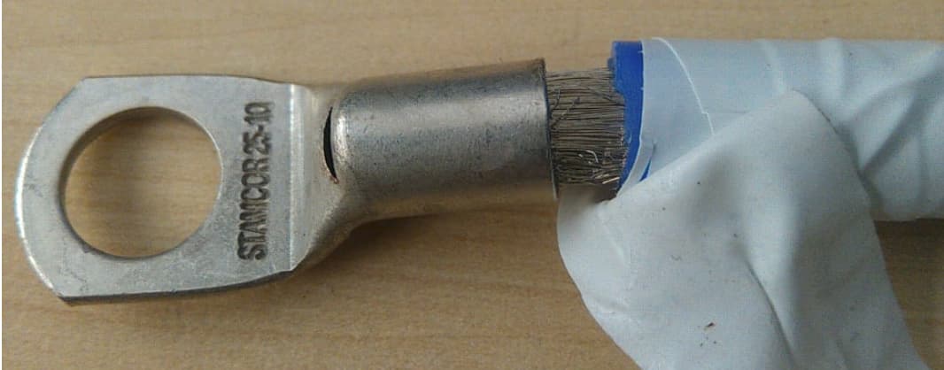
Yes, the flared lug opening makes it easier to achieve that. Otherwise, as I pull off the insulation, I wrap the copper strands together with insulation tape. Then the insulation tape can be removed after the start of the copper strands are inserted into the lug.
Wrap up the strands as you pull off the insulation. So when the insulation is fully pulled off the tape wrap has essentially replaced it. Then insert the tip into the lug and you will be able to unwind the tape as you further insert the copper strands.
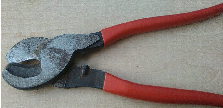
It goes without saying you need a clean cut on the cable.
A set of these will work in a pinch:
I have tried it before, reading you say it @Phil.g00, a penny dropped … I went “all-out” to keep the tape very very tight. YES!!!
@Richard_Mackay , that blue wire is from the BMS I bought, very flexible wires, 2 x 25mm (4AWG). The lugs were too small for the BMV’s connection point. Sorted!
I’ve got these, got tired issues cutting like 50mm2 wires.
Thanks for the advises. I was thinking about adding some additional wires (from external cable) to the lug together with the wires of the pigtail cables in order to fill up the free space, if the pigtails are standing very loose in the lug before crimping.
Speaking about this JBD SP25S003-16S, 100A (come back to the main topic), I have this isolated version of FT232RL. I hope this will work.
The BMS has only two pin RS485 JST on the PCB. I suppose the ground is not used by the BMS, I do not know why?
The ground is connected to the screen if there is one…
All serial comms (except RS232) is a differential signal. This means that the data is determined by the difference in voltage between two wires. The voltage wrt to ground is irrelevant. This system has high noise immunity.
Crimping is one of those difficult things to get right. My suggestion to those who are keen to give it a go is to solder the connections. If you use flux solder (I haven’t seen any other for years!) you are bound to make a solid connection…
When it comes to the current levels in solar systems, I am deeply against soldering. I come from a long background of soldering everything, even today I will sometimes tin the wires before I attach a (new) plug to an appliance, but there is a caveat here: The base of the 3-core cable is clamped down so that there is no relative movement on the individual conductors, which prevents the strands from breaking off where the solder-wicked ends (capillary action always pulls the solder up into the insulation).
Additionally, in a high-power conductor, once it does start to heat, it only needs to reach around 250°C (depending on the tin content) before it starts to desolder itself.
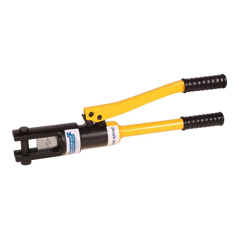
Similarly I am against crimping with those hammer-crimpers. I’ve seen my dad crimp a welding cable with a hammer and a bolt, and it lasted many years, but you don’t have the required control to make a good connection.
What you want to do is squeeze the cr*p out of that conductor, to the point that the individual strands form a solid cold-welded whole.
So basically: If you must solder, then only low-power wiring, and do something to support the joint if it’s going to experience vibration or movement. If you can crimp, then rather crimp.
Also, as soon as you have the tools… you’re never going back to soldering. Man, crimping is so much faster…
You crimp it only once, it forms a hexagonal shape roughly as wide as the lug, and as a bonus it imprints the size on the lug. With this kind of crimper, you should NOT crimp it a second time, as this can actually reduce the effectiveness of the crimp.
It is also extremely difficult to screw up the crimp.
