Yup. There are multiple reasons for BMSes to disconnect the cells from the DC-bus. High voltage is the most common reason, but not the only one.
And there we have it.
Using the UART connection, by unplugging the Bluetooth, connect the FT232:

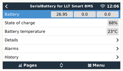
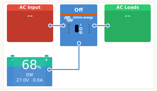
Comms achieved to the Venus Rpi:
Thank you @Louisvdw for your patience and assistance … and the software!
Now, I always push the envelope … 
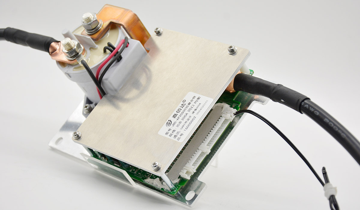
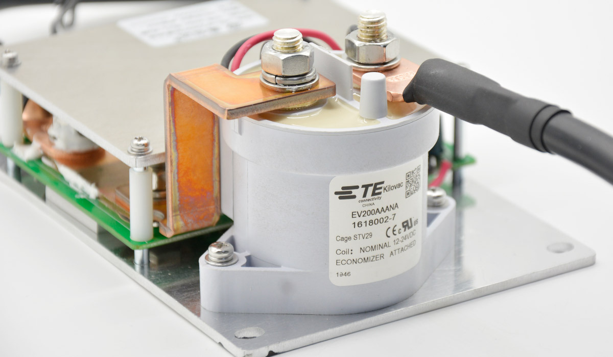
My thinking is, with this type of BMS:
- Bluetooth / UART included
- Add CANbus for $5
- BMS is 24v and 48v out of the box and can handle different cell technologies - to be confirmed.
- Ample balancing amps for more cells in parallel.
- Built-in shunt.
So I’m thinking that the next level would be to have the CANbus communication working with the Venus, leaving the Bluetooth available for checking more details on the BMS, and like programming/tuning the BMS on the fly. I’ll just leave that thought here. 
Now to sort the 24v 800va with a 100ah lithium bank:
Option 1: Get a cheap 24v BMS with a BMV that I will have spare IF this new one’s shunt is as accurate.
Option 2: Get another one of these.
Will take the weekend to sleep on it.
3 Likes
But if I recall correctly, Bain asked his BMS supplier to put the Victron CAN profile on there, so in theory just wiring it correctly should work already.
BMS is not from Bain … he gave up on me testing. ![]()
This new BMS is much better in my opinion.
It might still be interesting to first look what the CAN-bus on that BMS sends out (I do remember correctly that it has such a thing, right?). No point in reinventing the wheel.
If you do need to reinvent it then, then I would look into making a “converter box”. Probably some kind of arduino with a CAN-bus shield, and some basic code to convert the comms with the BMS into the equivalent CAN-bms frames. I’m just not sure where you’re going to hook into. If you want to keep the bluetooth, then you also lose the TTL-serial port. So you’d have to use whatever other port is on the device. I think Louis indicated that some of them have an RS485 port too… ie the SOC (system on chip) of that thing likely has two UARTS.
Well… have fun ![]()
Looks like they either put a RS485 or a CAN port. On this one TTT requested the CAN, so there is no RS485 (we tried already ![]() )
)
Send you the specs of what their CANbus sends … obviously it would never work that I can simply “plug and play” the CANbus into the Venus. ![]()
I’m not THAT lucky.
Have made it easier to swap between Bluetooth and UART connection, thanks to ideas from Louis.
For the moment I would leave the Venus out of the equation until the bank is balanced, BMS is programmed to my bank and all that. Need Bluetooth for that.
Then once the bank is balanced and settled THEN I would use the UART connected to the Venus and see how that goes … whilst I manhandle someone into building me an interface for the CANbus.
They do have a CANbus interface box too, what it does I have no idea. But even if I got one, it still does not mean it is Victron compatible.
As I said, IF this BMS is as good as it says it is, no 1, my DC Ripples are gone and 2) the bank is balanced and 3) BMS being programmable and 4) interfaces with Victron via CANbus whilst using Bluetooth, I simply cannot see why newbies should not go for these ones, making them plug and play, 24v or 48v, and as I also said, IF I’m right, you can connect other lithium cells than just LifePo4.
Opens up a huge amount of options.
There is the option to consider a thought to form an idea to contemplate to maybe think about enhancing your software to read the CANbus data via a Arduino (… Arduino being Plonkster’s idea) …
OR I can order a 2nd one with a RS485 port (If they can add one) … if 2021 is not like …

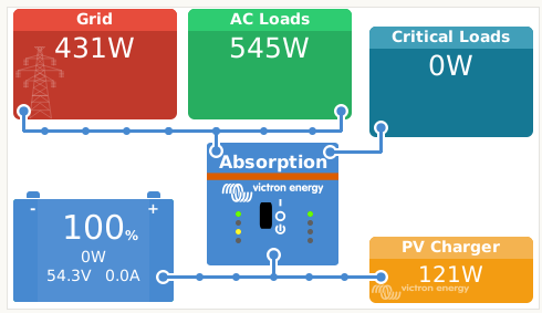
Right, new BMS is in, AND NO SMOKE LET OUT!!!
Using Bluetooth for now with voltages set on Inverter / MPPT / BMV as per Plonkster’s prior suggestion.
Bank Size: 48v 150ah
Bulk : 55.2v
Float : 54.4v - later will make this 55.1v as there is no float with lithiums, as per internet.
Charge Amps: 50a
BMV:
BMV Charge Efficiency: 99%
BMV Peukerts Exponent: 1.05
BMV Charged Voltage (0.3% below Absorption) : 54.9
BMV Tail Current: 4% 2% (~2 to 4%)
Discharge Floor: 20%
BMV Charged Detection Time: 3 (~2 to 5 min.)
Inverter: State of Charge when Bulk is finished: 95%
Also installed 75mm2 cabling and all the lugs are crimped 100% spot on.
My bet is it will work, as this BMS has 85v ceiling, and not 60v as the Daly had.
Let’s see if the DC Ripple is now gone … happens with full batts and low wattages.
Notes so far:
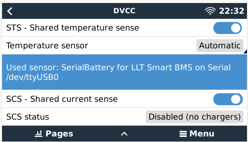
BMV shunt is more accurate than the shunt in the BMS when watching the amps going into the batts. BMS is lower than the BMV. Will keep on monitoring.
BMV measures first, then BMS shunt.
Ps. If I get the 2nd one, use this one for the 24v MP800va (… and as spare for main system), will order one with an RS485 port that can work the same time as the Bluetooth, as it apparently can be done … translation taken into account.
Once the settings are in you don’t need the bluetooth connection. All the important info is displayed in the Venus system. I rarely connect the bluetooth now. Just when I want to play around. ![]()
I’ll leave that for someone else to do. My driver is for a serial connection via software (no hardware needed).
I’ll leave the Arduino CANbus stuff for @justinschoeman ![]()
Try and see if you can figure out the difference pattern. We could always compensate for this in the driver. I also saw differences, but don’t use a a BMV (just the Multi) so can’t get real usable values.
1 Like
That is 100% true … but like with the Smart MPPT and Smart BMV, which I tweak and check via Bluetooth, brought me into the 21st century and made me lazy. ![]()
CANbus seems troublesome to get working … fugure I will do the RS485 port next, as I need a 2nd 24v BMS in any event.
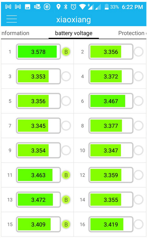
Right, found the cell that causes the problem … it hits 3.658v, and that would make the Daly stop = DC Ripple.
I think you, @plonkster, called this one too.
FWIW, got a graph per cell to see all the salient data per cell too and can see the overcurrent events recorded. Two so far.
How to make it happen … when seeing the batts are full = BMV shows little to no current going into batts:
Can then wait for specific smallish loads to go on/off, but that can take days.
Or I can set it to “FeedBack” with the batts full. Instant Ripple.
Or I can set the system to “Keep Charged” - this is what I did.
The new BMS handles it like a Pro. Beeped to warn me, I nearly died …
The next move was to see how long it takes to balance/bring the cell below 3.6v. Seeing that this BMS can handle up to 260mA balancing current … well it took minutes to bring that cell down.
Next is to see how long before the entire bank is in balance.
Here we are going into more sane voltages … will see how long it takes to get all the cells full.
BMV is at a perfect zero, so I assume the above all happens internally:
While that is high, it is not dangerously high. Some commercial batteries go way higher than that. BYD for example will let you go up to 3.8V on the highest cell before it complains. Pylontech is more wary, they stop you at 3.6V.
Secondly, it is normal for one cell to go higher than the rest. It is inevitable really. When the battery is very full, one cell will always sit a little higher than the rest. That’s simply the chemical reality: The capacity of the cells are not exactly the same, so the one with the smallest capacity spikes up first.
In a well balanced battery, your lowest cell will be within a stones throw from the highest one. For example, just this week on a well balanced BYD Premium I noted the highest cell at 3.6V, while the lowest one was at 3.52V or something like that. Less than 0.1V between the lowest and highest cell, with the other 14 cells somewhere in the middle. Nothing wrong with that…
Lastly, this is where the balancer topology comes in. If you have an active balancer (A DC/DC converter that sucks charge off the high cell and pushes it into the lowest one), then all that is required to balance the battery is hold the voltage at a point where the highest cell is around 3.65V… and wait for the balancer to do its job. If you have a passive balancer, then you actually need current to flow for the balancer to work, so then you want to alternately discharge and charge it, keeping it within that window where there is a voltage difference between cells (so the balancer can do its job).
With a good battery that can control the charge voltage properly, you can usually just run the system normally. The balancer sorts it out over several weeks, slowly upping the max charge voltage as the imbalance disappears. Sadly there are very very few BMSes that can get this bit right…
Having gone camping for a few days, on @Gman advices, I connected a 12v car bulb onto cell one this morning.
Although the bank overall is better after a few days, I still got warnings on Cell 1. From like 96 per day to 13 over the weekend.
I’m a wee bit miffed and have now learnt a “let’s not negotiate” lesson.
For although I did measure the volts over time, always fine, it is NOWHERE as accurate as having a BMS that shows each cells voltages and then peaks when one does not test at that moment.
The “let’s not negotiate” lesson is you have to have a BMS that shows you voltages. If you don’t, good luck from me who could have lost a MPII 5kva over time due to the BMS protecting, as designed, causing a DC Ripple, in my case Ripples.
Thank #*($&% this BMS simply warns.
Have a bit more faith. The reason it turns off on a high ripple is to protect your appliances, because making a clean 230VAC gets harder.
Very few commercial BMSes report cell voltages. We’re only now beginning to see some BYD models (and Pylontech is rumoured to have it in new firmware) beginning to support that, and only highest/lowest cells. Bit despair not, this is what you need. You need to know how far the highest cell is from the lowest one. In my experience, you end up with 15 cells at the same voltage and one cell at 3.6V+. And again, this is no reason for concern, as long as you have a way to cap the voltage at this point so the BMS can sort out the imbalance.
1 Like
Oh, and on this topic. Something that some installers have been asking for will make it into 2.70 soon.
1 Like
If @Louisvdw can bring that into his software too … ![]()
I’m floored. ![]()
Getting 2 x BMS’s in with UART/Bluetooth and RS485 ports.
The one I have now, will go to 24v system, as that system may become portable.
Then I put this new model onto the main system, as I can fasten it easily with the batts.
My driver already does have cell voltages. There is just no place to put them in the VenusOS which only have space for the min and max cells.
But as @plonkster mentioned you don’t really need more than the min/max. That will just be interesting to see. Not much you can do with it. Perhaps in future you can build some interesting nodered flows with it.
1 Like