I am using a Daly Smart BMS for my DIY battery build. I chose it because it has the best reputation among the cheaper BMSs available. Unfortunately, it is designed primarily for electric vehicles, so can not communicate directly with an inverter.
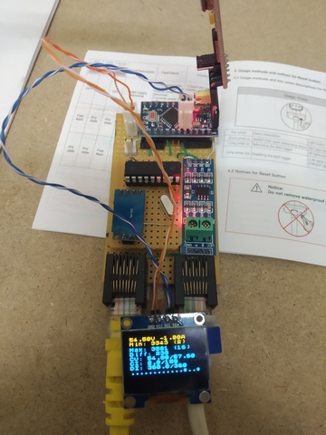
To get around this, I am using an Arduino (pro-mini in this case, but just about any 3.3v board should work). It is connected to a MCP2515 (using the reference design from the datasheet in my case, but any MCP2515 shield should work) to communicate with the inverter, and a MAX3485 shield for RS485 comms with the BMS.
Basic connections are documented in the source code. Largely it just relays the BMS outputs to Pylontech compatible CAN messages.
The trickiest bit (which would probably require some tuning per installation) is in derate.h, which is responsible for reducing the charge current/voltage if an imbalance occurs when cells are nearly full. These algorithms are developed experimentally to the requirements of my Deye 8kW inverter. Basically, then inverter is a lot better at controlling charge voltage than charge current, and the inverter HATES rapidly changing targets, so there is a lot of hand tuning involved to make sure that the outputs work well with the inverter, without risking overcharging any cells.
It is not really directly usable as-is, but can serve as a starting point for someone developing a similar protocol translator.
The Daly BMS is just battery protection and reporting, it does not do charge control. The inverter does charge control, but it needs to know the charge parameters in order to control it. The derating algorithms just take the measured BMS data and set up charge parameters for the inverter to target.
Smarter BMSs have this built in, so would be a lot easier.
Not really - the BMS still has the protection algorithms, which prevent any serious damage, even if I messed up horribly. The idea is to control the charge parameters so that you never reach the protection limits. Hitting them a few times is not an issue, but if you rely on them for cycle limiting you will seriously reduce battery life.
Just a titbit for sharing.
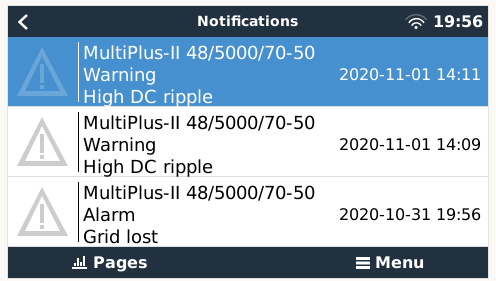
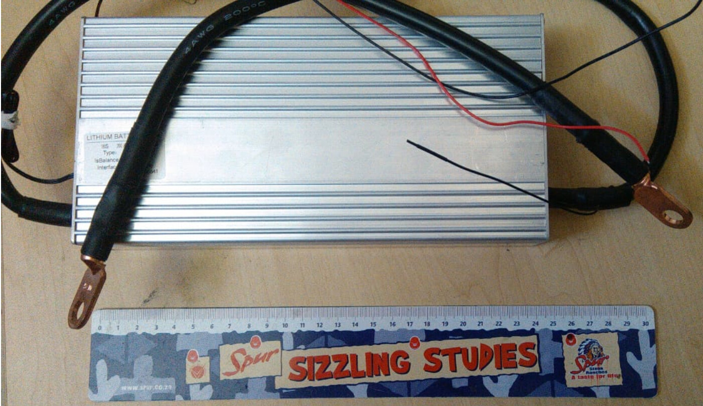
I have a Daly BMS, the 120A 16S 48V one that does not interface with Victron.
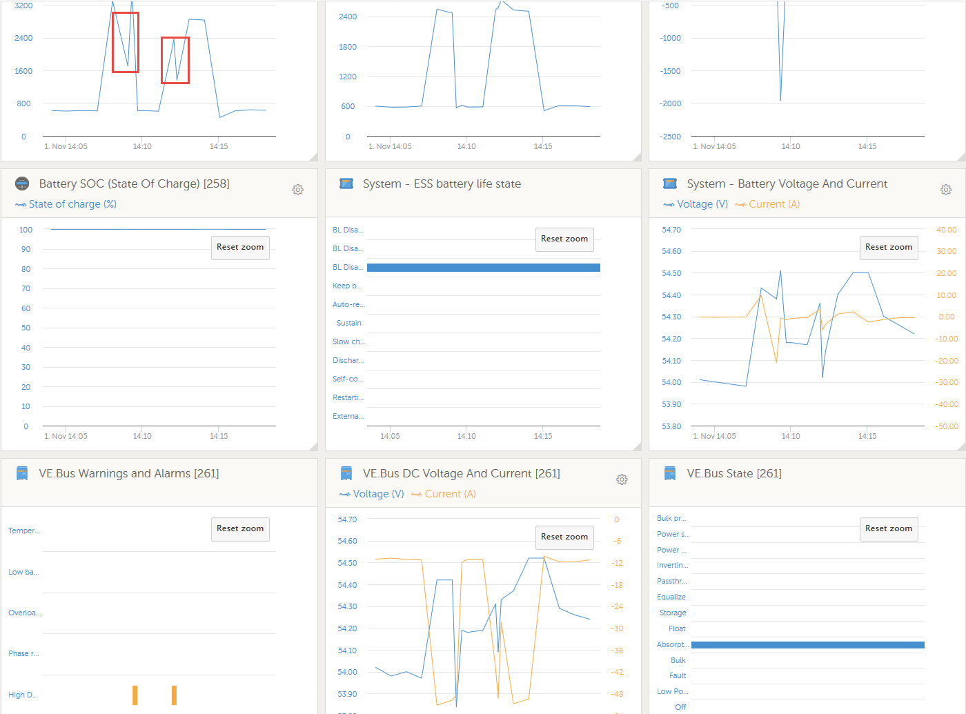
Nothing wrong with them but o boy, if you don’t drop the charging volts to like Bulk of 54.5v and Float of 53.6v, you get DC Ripples when the BMS does what a BMS must do ESPECIALLY when the batts go above 95% based on a BMV SOC.
Allegedly the reason is because they can handle up to 60v(?) or some such.
Was informed much later that Victron recommends 80v-100v and 60 000uf for a BMS.
The 100% SOC is bad mojo for my Daly.
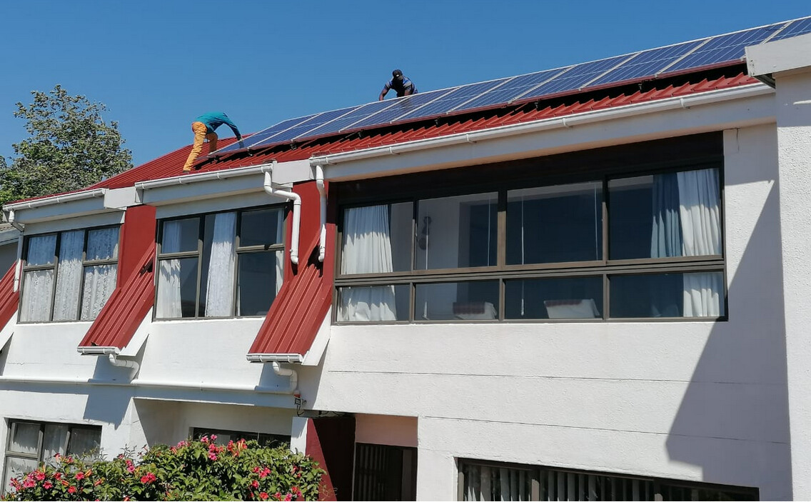
And because I know I needed 500w more, asked Jaco De Jongh to install 2 x 355w panels for me, thank you Jaco(!) this past Saturday (now have 12 x 350w).
So now I get to a 100% SOC faster than a diesel Ferrari even after I have extended the heating of geysers from 11-3pm to 10-5pm, so yeah, I now have to sort this again … find that sweet spot.
DC ripple happens because you’re running without a battery (the BMS has disconnected it from the DC bus). There are other bad things that might happen too when you run without a battery. EG starting a large load my plunge the whole house into darkness as the DC bus dips too low…
Ditto, is what I’ve been saying i.e. BMS ditches it all at the most inopportune moment.
Only way to solve that with THIS Daly BMS is to drop the volts … or if you don’t want to, then better one steers well clear of fully charged batteries.
It will only disconnect at such a low voltage due to cell imbalance.
One of the problems with the Daly BMS is that its balancer is pretty useless. It has a very low current, and only starts balancing right at the end of the charge cycle.
You might want to consider manually balancing the pack a little, or adding an active balancer on top of the Daly.
Thanks Justin. Plonkster said the same to me a while back re the low balancing current.
I have considered getting an active balancer from LithiumSA … but opted for a BMS that can handle up to 260mA ito balancing, the one we spoke about briefly re the CANbus interface.
I also suspect the max volts of 60v is a real issue.
New BMS can do either 75v or 85v, depending on the one they shipped.
Bottom line, me and this Daly, on a Victron system … No. Just No!!!
It must go.
I’ll manage the SOC and volts till the new BMS arrives … it is on its way.
Has a temp sensor, built-in shunt with Bluetooth (+ software), and supposedly a UART port and a galvanically isolated CANbus port added IF the lady and I understood each other.
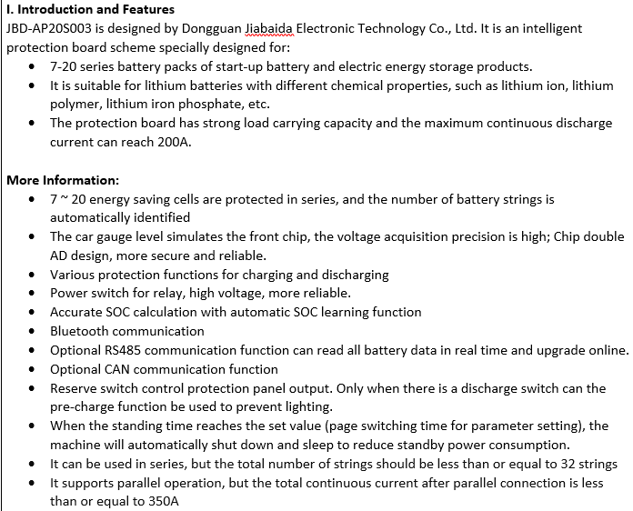
I’m reading that one can connect between 7 - 20 cells, the cells either being lithium-Ion or Polymer or Iron Phosphate … it automatically “sees” the number of cells and type … Yes/No?
Series and Parallel connections … Geez!
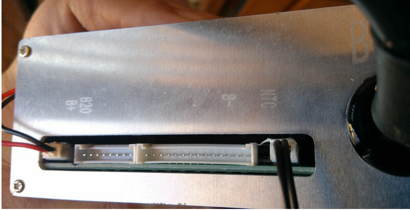
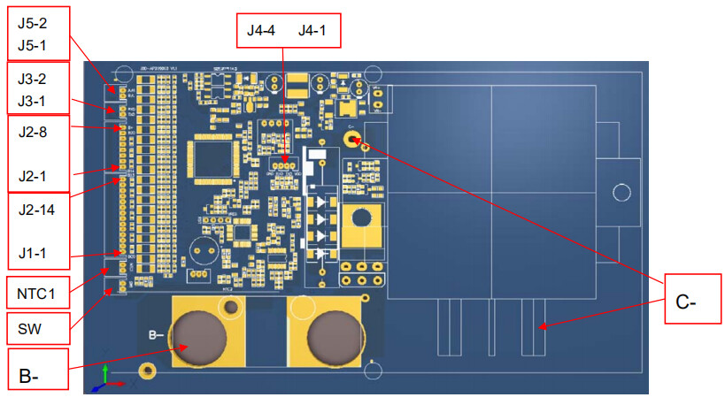
I also note that it is marked B- to the right, and B+ to the left. I assume this means the most negative cell connects to the right-most terminal, and then they follow in sequence with the most positive cell to the left. And it goes without saying that if you mess this up, you’re going to break the balancer.
The one marked NTC, I assume that’s a temperature sensor?
B- is the negative pole of your battery yes. B+(or B20) is going to be the positive pole. The rest is all in sequence. The lead plugs should have a black and red cable on those 2 extreme points to help you with that.
Also: NB: Connect the leads to the battery cell poles, test the voltages jump from ground in sequence with your multi meter AND ONLY then plug the lead connector into the BMS!
NTC is the temp sensor, yes.
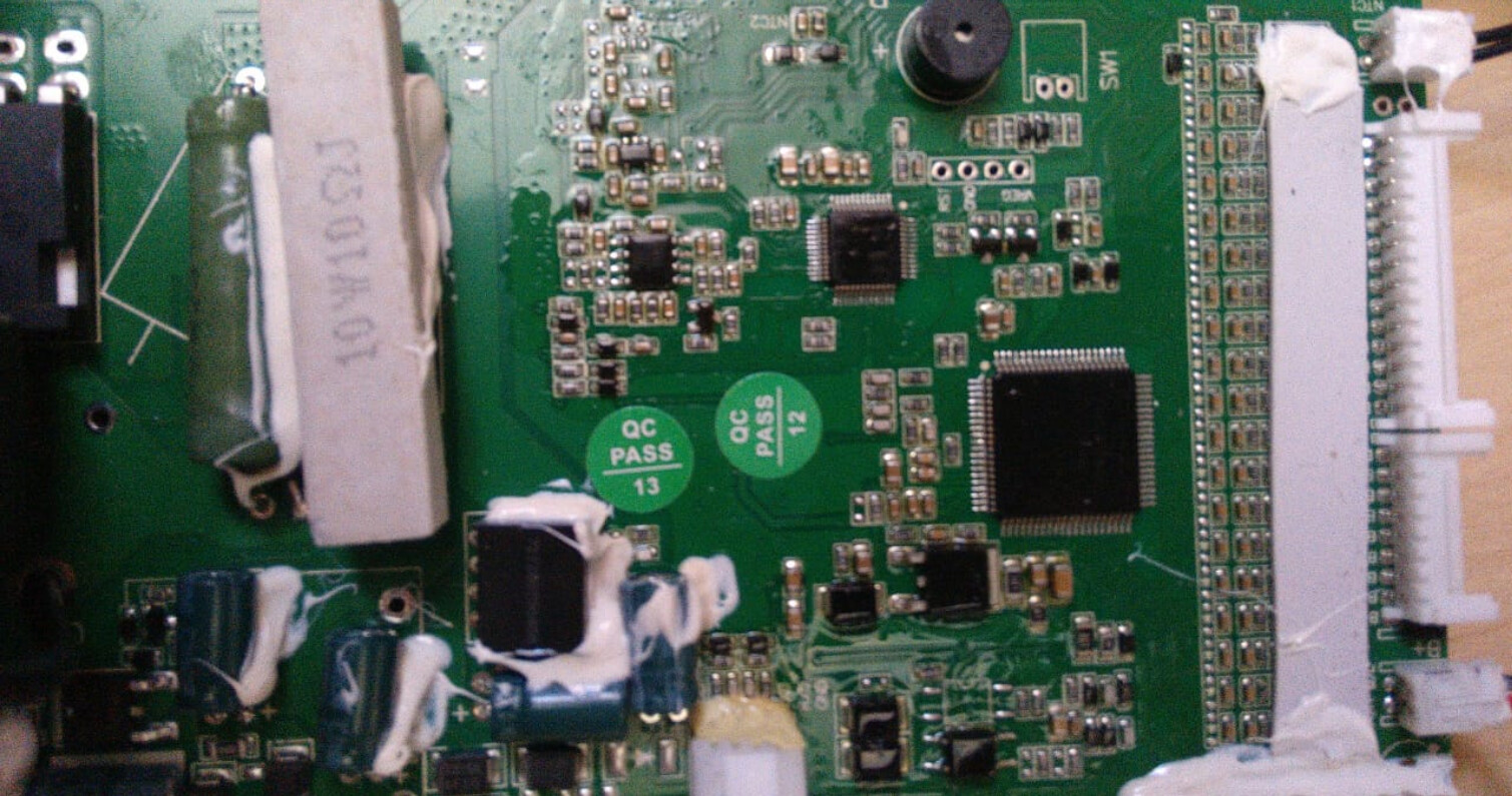
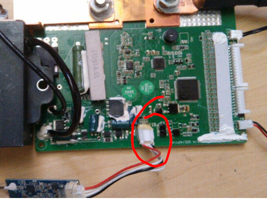
Then to answer the UART question: Here it is
The bluetooth is connected to it. That is the same as with my BMS. So I have to switch between the bluetooth and my RS232-USB that connects the serial battery driver.
If you had the RS485 extra then you could have use that instead and did not have to switch, although some implement the CANbus as a RS485/CAN socket, so check for that also.