I wonder if perhaps the bluetooth part of it is just rfcomm… essentially serial comms over bluetooth. Used to be quite common with cell phones, that is how you dialed up to the internet from a Linux computer using a mobile phone.
If that is the case, then you could possibly set up the serial port (though lots of extra software that is not in venus would have to be added), that would land you a /dev/rfcomm0 device which would presumably have the same serial protocol.
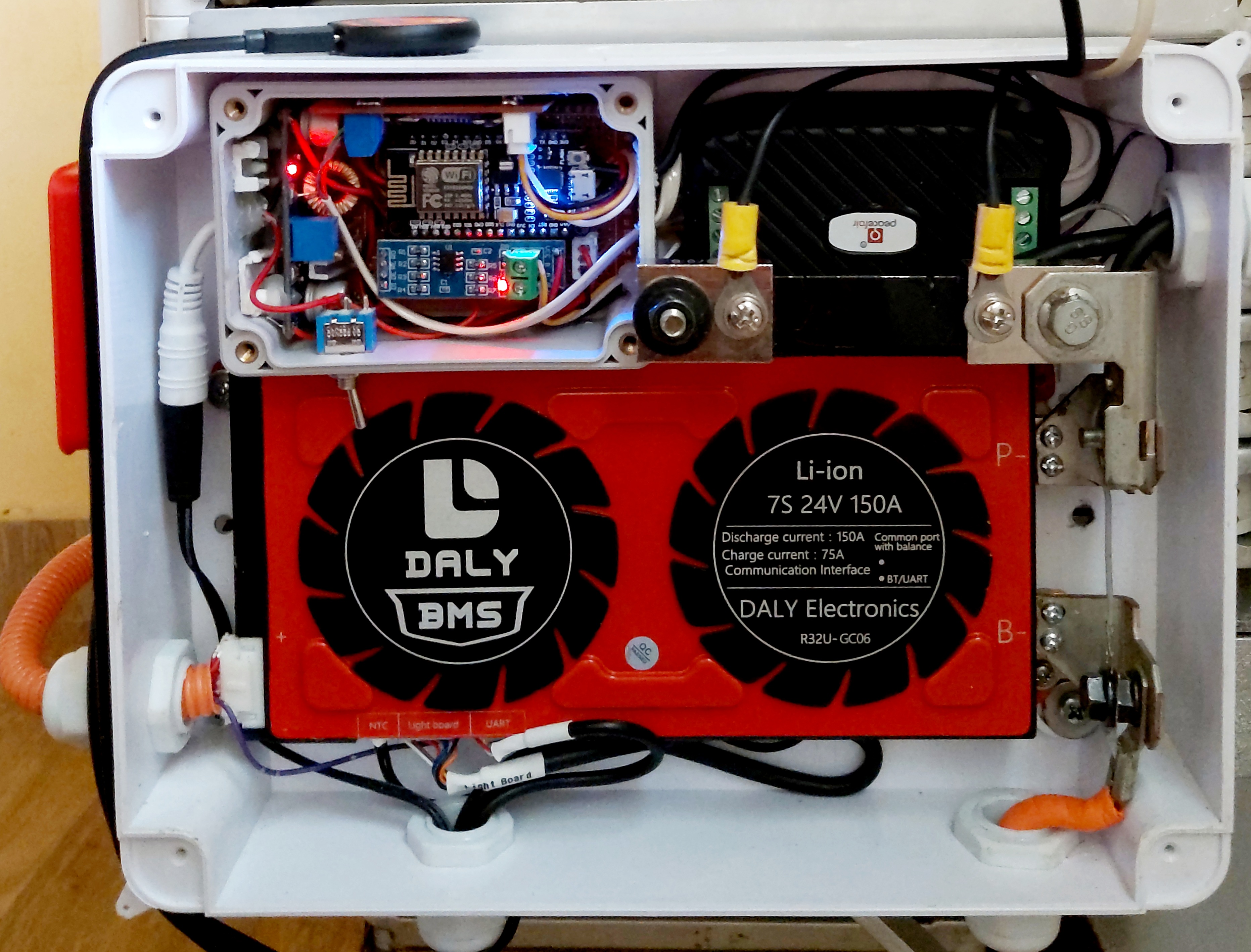
Yeah, there is that tiny matter with me blowing one BMS, and I swear the 2nd one was faulty. But, I touched it.
So I’m wondering, who want to test this one to see if their software works on it? @Louisvdw for UART and @justinschoeman for CANbus (IF it has the CANbus port)?
Before I install it …
Yeah, that was more for @Louisvdw than for you. He may discover that his software can also run over bluetooth (with the addition of a few bits of software that’s been in Linux distros at least since 2003… ).
I am 99.95% sure that this is the case. I do think it will work without skipping a beat with a rfcomm, but my bluetooth dongle that I have laying around did not want to work on the Venus Pi and I lost interest in the bluetooth part for a while. Now if someone can make the bluetooth work on the Venus Pi2/3/4 then that would be very interesting.
PS. The ANT does use rfcomm for the bluetooth connection. This is where I was starting to play with it. But I have no ANT venus interests yet.
The smart Daly looks to use almost the same protocol as these LTT/DJB BMS (just some adres changes)
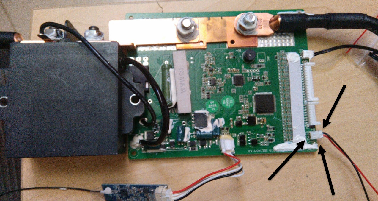
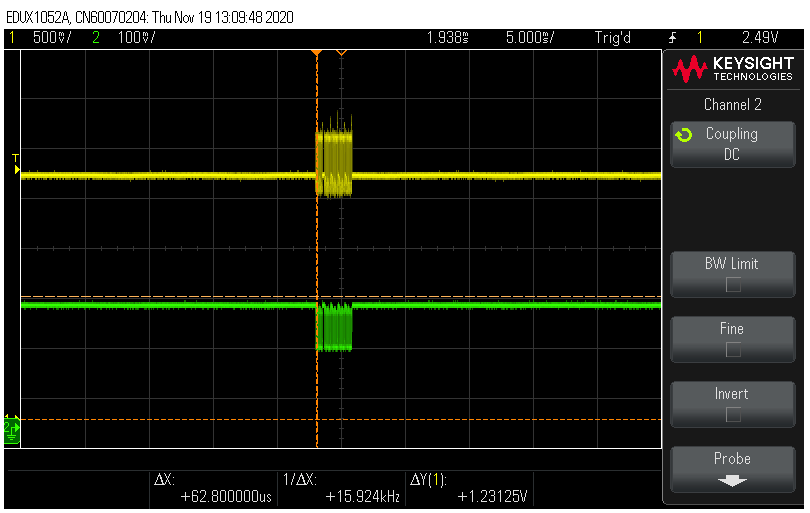
CAN bus is a differential bus. So one line always pulls up while the other pulls down, and the signal itself is the difference between the two. The above was me just messing around to see what I can see. The particular scope in question has no CAN-bus decoding capabilities, but you can at least see if the signalling is healthy.
Unfortunately, that won’t tell you if it is RS485 or CAN. Both are differential, and H/A are both low when bus is idle, and L/B are both high when bus is idle…
Also, if it is like the Daly, then it is a slave device, and then for RS483 or CAN, it won’t produce any signals until it receives a request.
Hi @justinschoeman, i really appreciate if you could share the pin connectivity from Daly to MAX485 to Arduino. I tried to get the feedback from daly but was not successful.
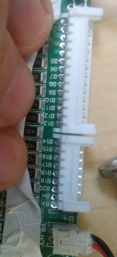
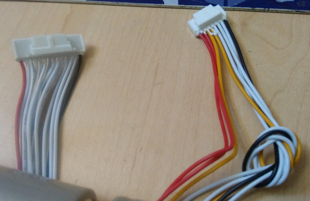
Mine came with an RS485 fly lead with labelled wires… There have been substantial changes between models, so I am not sure it would be reliable, but you could try the RS485 section from this manual: Part 1 - Daily Smart BMS Manual.pdf (2.2 MB)
Also, double check that you did order the RS485 option - that could be why the lead is not included?
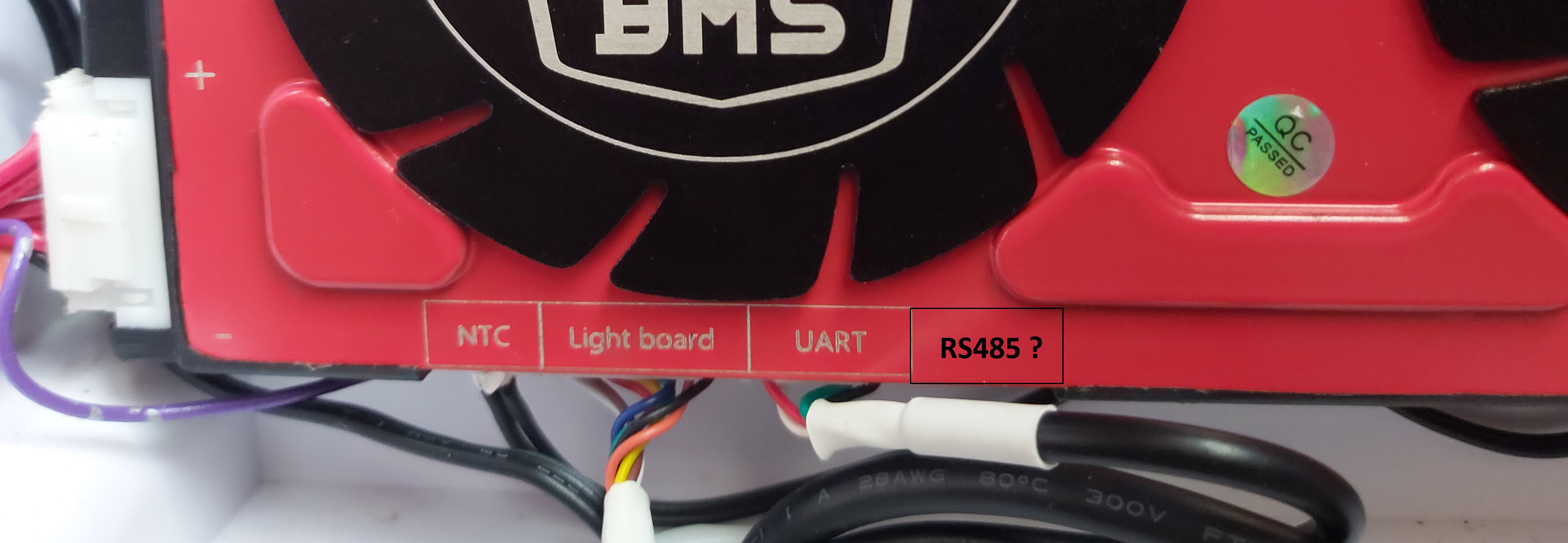
Look on the label, next to ‘Communication interface’ - you see your BMS only lists BT/UART. This means the BMS was ordered without RS485 connectivity, and you can not connect it to an RS485 transceiver.
You should be able to do much of the same stuff over UART or BT, but I have not played with any of that.
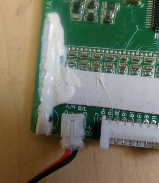
Thank you Sir. There is an unlabeled 5 pin port next to UART on my BMS. could you please tell me whether your fly cable connected with the 5 pin port ? if yes which one has to connect with MAX485’s A, B, and ground ? i will give it a try
It is connected to that connector, but I did not take a detailed enough photo to see which pins, and I am not going to disassemble the battery to check.
It is probably the same as is documented in the manual I posted above.
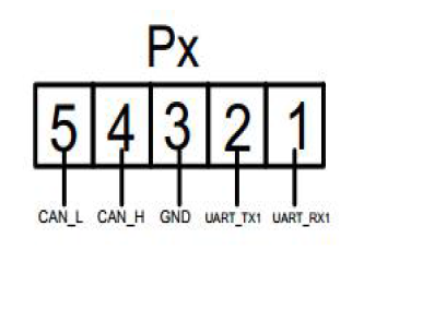
Hi @justinschoeman, I went through the official documentation of Daly and decided to stick with the RS485 connection as per the below pinout diagrams. I did all the possible connection to make the coding work and tried to connect with my ESP8266 (CP2102) with the use of MAX485 serial converter. But unfortunately nothing really worked so far. I’m not a hardware expert and still in a doubt whether i have selected the right connection between the pins or not. I saw you have used Arduino Pro Mini with MAX485 TTL. Similarly I need your your assistance to make the pin order correct with my setup. Can we directly connect MAX485’s A, B ports with Rx and Tx of BMS ?
On the coding, i did the below change and put the code running, but i’m getting only “Rx fail cmd 90!” on the serial monitor.