Possibly a question for @Louisvdw, but anyone feel free to chime in.
I want to measure big currents (600A) and I want to be able to switch them on and off.
I want to switch charging and loads off individually depending on conditions.
I intend to have 18 or 19 cells in series.
The functions that I reckon I already have with Victron and my existing gear are:
Temperature low and high cutoff is not critical,(there are has a temp probe options anyway).
I already have HA04 balancers that do up to 20A balancing. ( I’ll just overlap every 4th cell with a HA04).
The high voltage charging threshold is settable on the Victron. ( which I prefer)
The low voltage cut off is settable on the Victron. ( which I prefer)
I can see the current and state of charge on a 1000A BMV. (Which I reckon is more accurate than a voltage assessment anyway).
So the functions I don’t have are:
I’d like to see cell voltages on Venus, that would be nice.
I need to be able to stop charging for a cell out of balance condition.
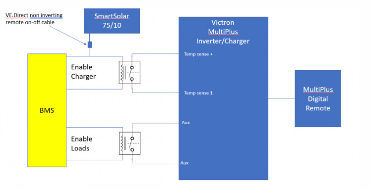
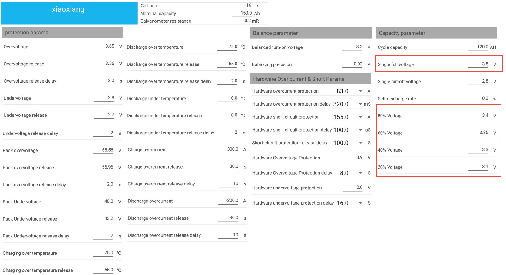
I found this little gem, and I want to use the built in facilities to do the switching.
I have two questions:
1.) I have not used a BMS, so my question to all that have used these aftermarket BMS’s, is what BMS can show me 20 cell voltages in VRM and has two discrete digital outputs, one to switch off loads and one to switch off charging? I also don’t want 600 amps passing through the BMS and I don’t want to be forced to use its shunt.
2.) If the above can be satisfied, am I missing something that I still need?
Sounds like you want to bypass the BMS to build your own BMS
No BMS shows you all the cell voltages in VRM. This is cause VRM only has an interest in the min/max cells. If you know those then you know your range which is all that VRM needs. The BMS then looks after the cells.
The exception to this is the driver that was created for the Chargery BMS. It display all the 16 cells on the Remote Console, but not sure that gets into VRM.
The BMS that @TheTerribleTriplet is also importing is for up to 200A and can take up to 20 cells. It also works with my driver on the GX.
Might be worth a look.
The BMS as charge and discharge FETs. These stop the charging/discharging when for instance a cell imbalance happen.
My driver also reads these FET flags and report this to the GX. This will then get passed to the charger (the Multi or SmartSolar) to also limit power generation to what the battery and system allow.
Well, so much of the functionality seem s to exist already, and I trust it because I’ve used it before.
I can live with that.
The chargery also has a 24S 600A option, but from what I’ve heard the VRM interface is a bit hit and miss. I don’t like switching with solid-state switches, they tend to blow closed circuit.
I think using the Victron itself to perform this function will be more reliable. The chargery does have digital outputs though, in fact, that diagram is based on a Chargery BMS.
It too light at 200A, ( I like that it’s a solenoid) but if I can totally bypass the current input and retain the voltage functionality, I’d be happy. @TheTerribleTriplet can you bypass the current functionality and does your BMS have digital outputs?
I think that FETs are a weak point, a good ole solenoid contactor is better, but then they draw a standing power. This is why I prefer to use Victron’s own internals.
Phil, what part of my Masters Doctatorial degree in “WTF NOT to DO!” did you miss!?
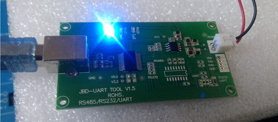
What I DO know, the BMS comes with a UART port for Bluetooth. Now one can disconnect it and connect that to a RS485 converter to USB, and connect it to the Venus.
OR like we do, ask supplier to add a RS485 extra, that we can use that port to connect to the Venus.
This batch is tricky, as there are 'n semiconductor shortage in China, but it SEEMS to me that can get them still in this order.
I’ll believe the code will work, especially when backed up by old-fashioned wires and switches.
The difference is I put the wires and switches in place, and somebody somewhere wrote the code. @Louisvdw & @plonkster present company excepted of course.
@TheTerribleTriplet,I am still reading up on it.
I am unclear does it just use the RS485 port to report to VRM for visual purposes, or does this communication actually implement charger and inverter controls?
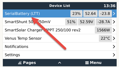
Louis software does it all as long as the Venus see the BMS. How it is connected, makes no difference, RS4895 port or UART, as long as the BMS appears like so on the Venus:
Ps. I even altered some of his parameters in his program on the Venus … must just remember to put them back after each update. Got a “picture” see.
@TheTerribleTriplet
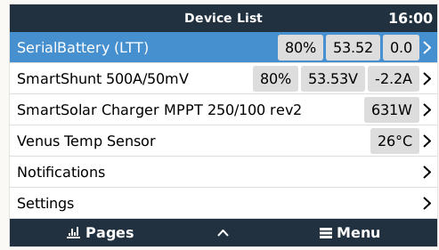
This is interesting, I see in your pic you still have the BMV SOC, that’s good because I want the current to bypass the BMS.
I want to keep the voltage data and use unbalance protection, I assume this BMS actually breaks the current rather than telling the inverter to shut down via 485 comms.
incidentally, they have a 30A 20S model, which is a lot cheaper and I have no use for the current path anyway.
Now I just have to figure out how to get a contact out of it.
Still reading up …
For me, the BMS I like so much, can go 24v OR 48v … just connect the balancing wires differently.
Jip, BMV is staying, I don’t trust the BMS SOC at all … it is like a Axpert, based on volts.
Currently, I run off the BMS SOC till the cells behave again, as they used to for MONTHS on end, or when I can replace 8 of them with the 280ah ones, the rest coming in the next order.
“They” say on can mix and match cells with lithiums, 150ah and 280ah … I’m going to do that, walk THAT talk.
Both. The driver updates the GX with all the data which you can see in VRM.
The GX will also use this data to manage your ESS system. This include limiting charge/discharge current, stopping charge if the battery is full and limiting the power production from your MPPTs to only what is required, or stopping charge is a fault happens (cell imbalance, etc)
All this the GX device will handle, but it can only do so if the battery’s data is available, which is what my driver enables. The readme for the driver has more details on all the features AND it has a picture or 2 for TTT
Both again. The BMS will tell the GX that it is full and this will stop the charging from the inverter/MPPT. If the charge does not stop, then the BMS will force a break to stop the charge. Same is true for discharge as well.
The only way I can think of would be to hook into the GX and read the data published there, as the BMS does not have an output other than it’s own out. But I guess you might be able to hook the BMS output to a relay to break the full circuit.
It’s not, but we had this discussion already in another thread :D. It does take the volts of a cell into account as well. Perhaps you must upgrade to Phil’s monster manual BMS he is building
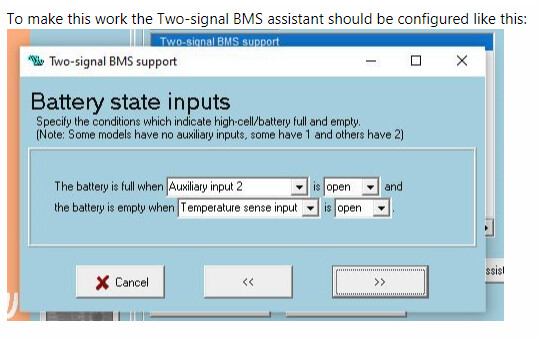
@Louisvdw, I have had a bit of a play with the app. I don’t need the overcurrent protection and want the system to use the BMV state of charge. I’ll make use of the soft voltage imbalance settings. I double up upon battery bank Overvoltage and Undervoltage cutoffs, but if the BMS overrules the Victron settings, I’ll do without that soft protection on the BMS.
This is good news, I think. I can get the 20S 30A cheaper version and drive an optocoupler with the BMS’s main contact. Which in turn will provide a hardwired digital input to the inverters and MPPTs.
( I may need 2 30A BMS’s so I can differentiate between load cutoff and charging cutoff).
From what I have gleaned so far the SOC from this BMS is only ballpark at best. It’s OK it won’t know my current in or out anyway.
The long and short of it, I think I can make it work, without having to trust FETs for switching heavy current.
Not an issue. In your GX settings the BMS SOC will be used if in Auto mode, but you can just change that and pick the BMV’ SOC to guide the systems limits.
Just be aware that your SOC will then not handle changes when cell imbalance happens when you do that (best to go read the thread on that details and make sure you know why the BMS SOC is better even though it might not work for your scenario so that you know what issue to look out for).
I have to disagree. This BMS SOC is one of the better ones. It use a shunt and is pretty accurate.
If you compare it to the BMV then you are missing the hole thing about lithiums. You are still thinking in terms of lead acid batteries and you are trying to limit your lithium to work like a lead acid.
Here is a post explaining the SOC from the BMS.
Screenshot are in that thread about how to change from the BMS SOC to BMV SOC and back. (few posts down)
OK, it looks like this BMS comes with RS485 and a UART and a Bluetooth module.
The RS485 converter to USB is extra.
Do I need this converter? Or put it this way, which is the more reliable comms channel?
Yes. This is the connection that the driver use. The UART is for the bluetooth. If you want the bluetooth and the driver connection you need the RS485. Else you can use a USB UART converter by replacing the bluetooth connection. Better to have both.