I have a couple of these 485>USB converters already.
1 Like
Just for those following this thread, if you were to believe the suggested wiring diagram of this jJBD BMS, you would be led to believe there is only one power contact on the FET versions.
There are actually two.
The suggested connections are B- (battery neg.) through a double row of MOSFETs to C- (charger negative). However, in between those rows of MOSFETs is another bus, that can be tapped into to P- (power neg.).
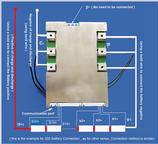
In other words, it is possible with a single BMS to differentiate between switching off the load and switching off charging.
The way it is suggested to be wired it indiscriminately switches both the load and the charging off for all protection functions.
I intend to use these two 30A output contacts not to switch current but to drive the Victron two wire BMS and use @Louisvdw 's driver to visualize and soft control charging in a Venus device.
So there you go, a 60$ solution, with hardwired interlocks and nice little numbers in VRM.
Happy day.
1 Like
Why not email them and discuss?
I have emailed, but got impatient and bought one. I am pretty sure, the only thing is the 30A smart version doesn’t seem to have the connection.
So I settled on this 40A version:
(It doesn’t have 485 so I got the USB converter box as well).
See where it is possible to tap in at the top.
1 Like
If I may ask a question regarding these BMS units.
I have 2 x 12vdc x 105amp LA batteries in series supplying 24vdc x 105amps to my 3kw inverter, I might add another bank of batteries to give me a total of 24vdc x 210amps at a later stage. everything works as it should.
Would it be of any value to install a BMS?
thanks
spiff
The better batteries I’ve seen use it to drive two MOSFETs (or rather a bank of each) so it can individually block charging or discharging. The MOSFETs go in series (cause a MOSFET always conducts in reverse through the body diode), and in that way you can decide which way you want the Diode to sit. Quite clever really.
What I really like about these batteries is that an overvoltage doesn’t cause things to switch off. The DC bus can sit at a higher voltage than the battery itself, and except for the possibility of DC ripple it usually does just fine. Conversely, on discharge, if you open the relevant MOSFET, the voltage simply drops out and the inverter’s low voltage cut-out kicks in.
Nope only for lithium cells, a BMS.

Yes, this is what I am seeing.
In between those two banks some BMS’s have a bus that can be tapped into. Effectively creating the ability to have to output conts.
What you have to be careful of is not all BMSs’ have this.
So, anybody that intends to follow my lead, make sure they have a BMS with B-, C- and P- terminals not just B- and C-.
A MOSFET is like a transistor, except instead of using a gate current to turn it on it uses a gate voltage. This makes life a lot easier, because to calculate the perfect resistor values to produce the exact gate current is a mission.
However, theoretically you could replace your cheap BMS’s Mosfets and beef up the current rails add a heat sink and switch 1000A, with the base PCB remaining the same.
In fact it wouldn’t surprise me if most of these BMS’s rely on the same PCB with just more pairs or more powerful MOSFETs being fitted.
Just solder wire on top of the PCB tracks to beef them up and it would be easy to replace the MOSFETs yourself and get yourself a 300A model out of a 100A model
1 Like
@spiff
I see you got your answer.
LA batteries have another characteristic, you want them all to age together.
The way it has been described to me, is that new batteries added to an old bank, very quickly age to the performance of the older batteries.
The conventional wisdom is to buy the whole LA bank at the same time, not build it up.
This is not supposed to apply to lithiums, they say. I don’t know, Lithiums haven’t really been around long enough to be definitive.
A little off-topic, but It’s not necessarily just a case of adding more MOSFETs in parallel to increase the current rating. Yes, MOSFETs are voltage controlled devices, but you have all sorts of things to consider. For example the miller capacitance, which causes the gate voltage to decrease as the drain-source voltage is decreasing during turn on (look up the miller plateau if you are interested) as you hit the gate threshold voltage, which means that the MOSFET actually tries to turn off again and during that time it isn’t fully on yet and could be dissipating a lot of energy if it is conducting a large current. In this case you need to dump quite a lot of current into the gate if you want to turn it on fast. There is a good chance it works fine at low currents and then the MOSFETs blow up when switching high current just because they can’t dissipate enough energy during switching. So, when paralleling lots of MOSFETs to increase the current rating, you also need to change the gate driver for one that can source and sink more current to turn the FETs on and off as fast as you could with fewer of them.
2 Likes
@ Stanley,
Good stuff to know.
I suppose an even easier way is just to drive a monster external DC-DC SSR.
EDIt: There appears to be wriggle room for more mosfer’s as apparently some lower rated BMS’s have blank spaces where more mosfets could be soldered.
I suspect a little googling or youtube and one will find it’s been done aplenty.
It doesn’t look like it’s a big issue to overcome, especially since there is no high frequency switching: https://www.youtube.com/watch?v=8swJ_Bnsgl4&list=RDCMUC6mIxFTvXkWQVEHPsEdflzQ&index=17
thanks Phil.g00 makes sense that they are matched. I will use these 2 till they die then either upgrade to lithium or by 4 LA again, my needs aren’t that demanding yet. If I go full off grid the lithium is the way to go
is there a way to balance the LA batteries?
For two 12V batteries, look for a HA02 on aliexpress, failing that so many people are switching to Lithium there may be one going begging if you keep your ear to the ground.
Edit: Actually I think the HA02 is for 4 batteries(48V) the HA01 is for 2 (24V)
1 Like
So where am I so far with my BMS hack?
A 40A BMS will give me two discrete outputs to switch 2 optocouplers or relays that in turn drive Victron’s two-wire BMS system.
A potential issue I see:
I want to use the BMV as the more accurate state of charge indicator, but I don’t for sure that with a BMS it is not going to overrule the BMV SOC. What I do know for sure, is have forsaken the overcurrent protection by virtue of bypassing the BMS’s current path and the BMS state of charge function will not work.
Can I do better?
I think so.
Apparently, the SOC published by the BMS is quite inaccurate. I have been looking at the Xiaoxaing app and the current can be calibrated. That may go a way to making the published SOC more accurate. I don’t think it will ever have the accuracy of a BMV, but it could probably be better than it is out of the box.
But that got me thinking…
How do I measure a potential 600A, with my 40A jobby?
Well, you see I have a 1000A shunt on my BMV, as a 1000A DC current passes through it, it produces +50mV or -50mV across this shunt depending on the current direction ( charge or discharge).
This tiny voltage is fed into the BMV, which in turn translates it back to the proportional current that shows its display and is reported to Venus…
Well, how does the BMS know what current it is passing? …Exactly the same way.
In its 40A path, there will be a very very low, high wattage resistance. I haven’t seen it but it will be there. It should be fairly easy to spot on the PCB.
If I take scratch the PCB tracks to take that resistance out of circuit. Then solder a pair of wires onto the tracks where the resistor was. I will be able to connect these wires to the voltage output of the BMV 1000A shunt.
I will effectively replace the BMS shunt with the BMV shunt.
Then I can use the BMV to calibrate the BMS current through the app.
I’ll have overcurrent protection again and a probably more accurate BMS SOC published to VRM, than it originally came with.
Hmm…
1 Like
@TheTerribleTriplet
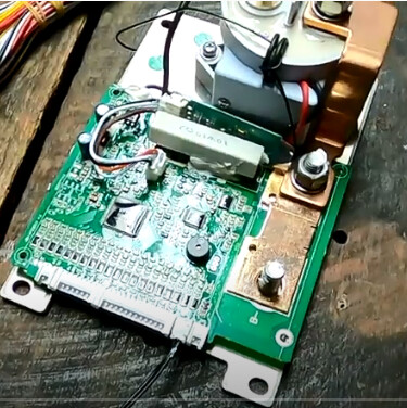
Here is a pic of your 200A without it’s cover.
Can you spot the shunt?
Jip, that is the latest model, cannot do 24v, and when I looked at them, they were not in a casing … yet.
Where did you source it from?
It’s been on youtube for less than a day.
Good timing.

1 Like
Are you referring to what value the GX device in an ESS setup will be using? You can set that in the GX to Auto or select the one you want to use.