I am aware that I will get “if you don’t know how, don’t do it” comments. I am however able to wire a plug and for some or other reason I was able to connect a Geyserwise controller… successfully.
I am also not looking for HA code, since I was able to find it on this forum and others.
I recently moved into a new house and it is time to change some things.
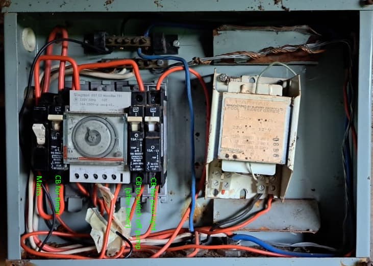
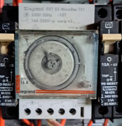
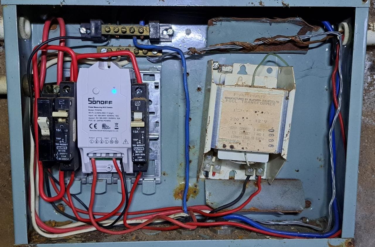
I’ve also jumped onto the band wagon with solar, pool is on non-essential and would like to take advantage of of my excess PV that is generated. To do that, I need to wire a Sonoff PowR2 switch. I tried to RTFM, but the pool’s manual is very cryptic and my French is somewhat rusted… And there are way too many live wires and to few neutrals. Currently the timer is not being used. I switch the pump on and off on my main DB in the house.
Firstly, do I leave the old timer? If so, I recon I can wire the Sonoff instead of the circuit breaker to the right of the timer. This circuit breaker switches the pool pump off if the timer switched the pump on. Thus the red wires would go to the "L"s on the Sonoff. Is this correct?
Neutral in would be from the top busbar. And neutral out?
Yes, it would probably better the rewire the whole DB as some stage… And I also know that the transformer is missing a couple of wires.
If the timer is not being used, I’d remove that first. Along with the CBI that apparently powers the timer.
That should leave a clean layout with two red and two black wires. One set goes to the pump. The other set goes to the transformer, which feeds the light in the pool (it is there for isolation, because the light in the pool is close to water).
To me it looks like there is a red and blue pair, along with an earth, entering on the right. That’s probably the supply from the main DB. The blue goes around the right hand to the neutral bar at the top. The red goes along the bottom left to the top of the left-most breaker (Mains).
Then there is a second red and blue pair, which I assume is the pump. The blue end goes to the neutral bar, that is correct. The red end either goes to a breaker, or to the time switch, in which case you can relocate it to the breaker when removing the timer.
Then I see a thinner black wire from the neutral bar, left hand side, probably powering the timer. That goes with the timer.
Then I see another black wire from the neutral bar, probably to the transformer? That one’s fine too. Red wire of the transformer probably goes to the other breaker, also fine.
Once that is all sorted out, the Sonoff simply gets its neutral from the neutral bar, and the live in/out connects between the breaker and the pump. Done.
One question: I assume this is protected by an RCD (aka earth leakage) in the main DB. Otherwise… I’d strongly advise installing one in the space left by removing the time switch.
@plonkster talk about a proper analysis! What you’ve described regarding the wiring layout sounds spot-on. I’m definitely then going to clean up the DB.
Yes, the main DB is protected and was tested about a month ago with the installation on my inverter (I think it trips on 20ma).
Just to clarify, apart from Live in and Live out, there is then only a single neutral on Neutral in?
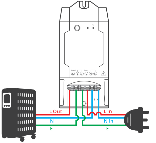
There will be 6 wires connected, but the earth and neutral are just a bridge (the in is connected to the out - see the lable above the connectors) so you can just wire those up externally. It will need to have at least one neutral connected to the Sonoff. The switching is only done on the live.
If you are unsure, wire it with all 6 wires as per the image below.
@Louisvdw posted a picture. The neutral connections on the Sonoff are simply connected to each other, they are there for convenience. You don’t have to put the neutral of the pump through the sonoff.
You can just wire both of them the pump and the sonoff to the neutral bar. The Sonoff needs a neutral to power itself, but in all other respects, it acts like a switch in the live conductor.
So all neutrals go to the neutral bar. Live goes through a breaker, through the switched terminal of the sonoff, to the pump.
Edit: Same is true of the earth terminal on the Sonoff. It is there for convenience. All earths should go to the earth bar in this case.
It will need to have at least one neutral connected to the Sonoff. The switching is only done on the live.
The neutral connections on the Sonoff are simply connected to each other, they are there for convenience. You don’t have to put the neutral of the pump through the sonoff.
Brilliant, thanks @Louisvdw & @plonkster. That’s what I just wanted to make sure of. You guys rock!
I only now had a proper look on the cover I could have save myself a lot of trouble and the both of you a lot of typing. I’m so used to 2 (or 3) wires in, 2 (or 3) wires out… but hopefully this will help someone else
Was on a similar path with geysers and spare power during LS a while back.
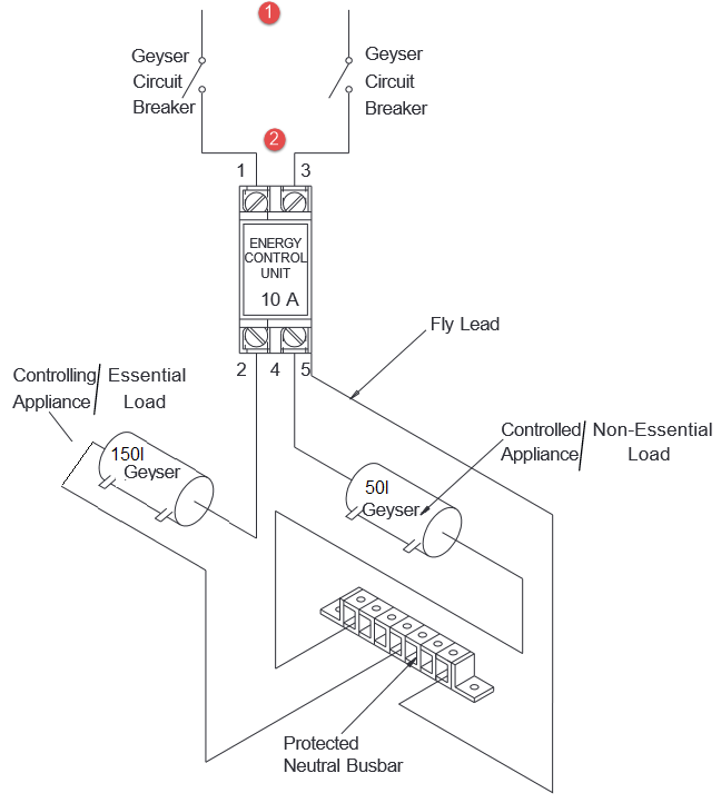
Dawned upon me one evening, instead of all the complications, just get a double pole changeover at the DB, and switch that circuit over to critical loads when needed.
Can automate that if one wants.
Went this far, being 2 geysers, heat one, then the other.
where the changeover was planned.
where the automation, in my case Shelly, was planned to switch the geysers on based on some automation.