I need to connect up my Solis Grid-Tie inverter to my Main DB in the house.
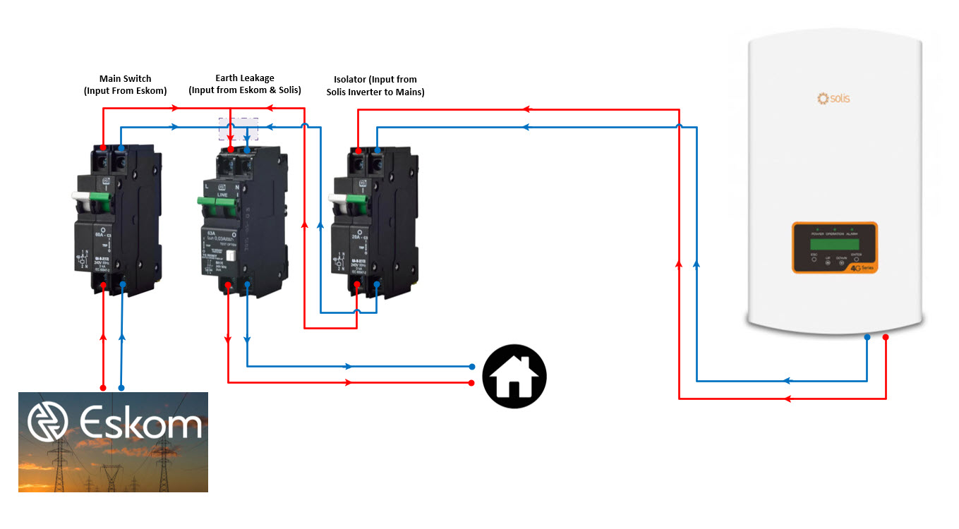
Can you please advise if it correct place would be to connect up the Inverter’s AC output after the main DB’s Main Switch but before the Earth Leakage?
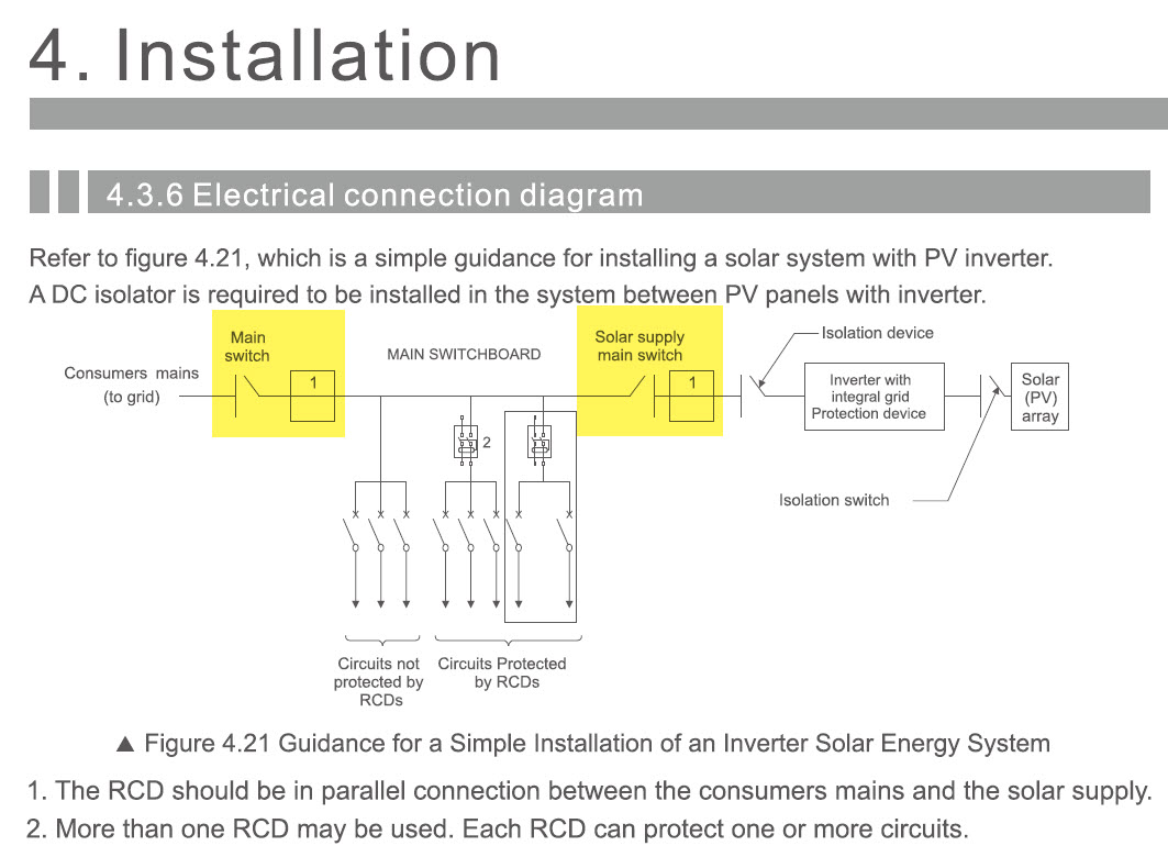
If I look at the installation manual then this does seem to be the case, not before the Main Switch and not after the Earth Leakage, so with the conclusion that it goes between the two so to speak as per the diagram and screen shot from the installation manual I attached below.
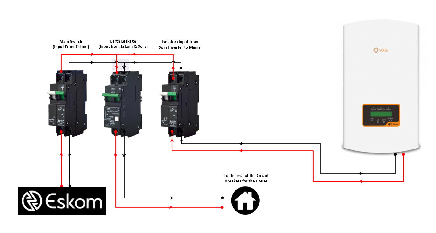
This is correct, and then install your CT on the main incoming live wire. I would only change one thing if i installed. I would bring the solis in at the bottom of the breaker and bridge the top with the grid. That way the top of all the breakers remains live even if you switch the breaker feeding the solis off.
So even thought the Solis inverter is technically feeding the mains (with power) one would still want to ideally bring it in at the bottom of its isolator so that the top part of the isolator is the “live” portion of the breaker in the case where the breaker is switched off but there is still power from the grid (Eskom)?
So it does not really change the way the wiring is done but more a case where one as a rule of thumb always wants the “live” portion of breakers to be at the top and the “switched off” part of it at the bottom?
I have noticed that on our Mains (from the Eskom grid) comes it at the bottom of the Main Switch, so that is the only exception, but for the rest one wants the “live” of the breakers at the top?
It’s good practice to allow the bottom of the breaker to be the dead side.
It makes it easier to wire.
Also… if you look around a bit, ABB has a series of breakers where the bottom of the main switch ties over to the bottom of the RCD (earth leakage) with a busbar kit, and then it runs in “reverse” to the top of the RCD where another busbar kit ties directly to the top of the other breakers. Thereby breaking the “rule” a bit, but it illustrates again how the direction doesn’t really matter.
Any deviation from the convention of connecting line to the top and load to
the bottom of switchgear is not recommended. Reverse connection is
allowed only if
a) it is specifically allowed by the manufacturer,
b) “load” and “line” are so marked that they are clearly visible during
maintenance, and
c) any contradictory marking is not visible after installation.
A grid-tied inverter is a “load” in this case, since it should behave as one - ie when grid is off, it is off.
When I went to the Electric Wholesaler to buy the AC electric wire I got 100 meter rolls of 6mm sq copper wire. The black wire had a problem with the PVC coating (were very thin at the one end, copper almost came through), so they offered me other colours, I opted for blue.
So I did the entire installation of the Inverter (AC wiring between Garage Sub-DB where the Inverter is and the Home’s main DB) with Red and Blue.
Is this going to be an issue for a CoC? (taking into consideration that my live is Red all the way through, the Neutral is Blue all the way through and the earth is either naked copper or green and yellow).
6.3.3.2 The means of identification for an a.c. circuit may be by colours or by numbers, as follows:
a) where colours are used
a neutral conductor shall be identified by black only,
an earth continuity conductor shall be identified by the bi-colour green/yellow only, or by being bare. Green/yellow insulated conductors shall NOT be used as live conductors under any circumstances,
a phase conductor shall be identified by a colour other than green/yellow, green or black, and
the colours may be applied at the ends of the conductor (of a multicore cable) by means of durable colour marking (e.g. insulating sleeves or by electrical insulating tape wound more than once around the conductor), and
b) where numbers are used, “0” shall indicate the neutral conductor.
In other words, put some black heat shrink on the ends of the blue wiring and you’re good.
I’ve seen people use tape of the right colour too.
Edit: I’m not sure about that “of a multicore cable” qualification. The qualified sparkies need to weigh in…
Thanks a lot, that makes sense, I am very happy that one can change the end of the electric wire to the correct colour.
I do have black shrink wrap, so I would have to just wrap the blue cable’s end (sticking out of the conduit) with black shrink wrap and I will make sure that all the rest of the wiring (between the Inverter and Circuit breakers) are all in black as that’s easy to replace blue with black, I was mainly worried about the long cable going between the house and garage which you have clarified with the ends to be marked
I think with the multi core cable they refer to the armored cable which can go in the ground without additional conduit, I also have some of that on the property (running underground to the gate motor) and noticed ours has four wires plus an earth of which one is also a blue wire.
My concern was that the allowance to simply mark the ends may not apply to GP-wire (general purpose house wire).
I’ve seen it done. In my own house, there was a black cable wrapped in its entirety in yellow and green tape to repurpose it as an earth cable… and apparently that is okay. I am a little concerned about the sparky who rocks up with a roll of tape, but no earth wire… but if it is up to code, then I suppose it is fine
Something that has bothered me about this configuration is that you could potentially overload the earth leakage without any breakers tripping: Assume you’re pulling 60A from the grid and your inverter is supplying another 20A, then you could potentially be pulling 80A through the earth leakage. You could put in an earth leakage with overload protection, but those tend to be expensive.
@JacoDeJongh How do you deal with this (if at all)?
Normally the loads in your house is less than the 60amp supply. In very few cases, unless you added a bunch of Aircons ext you will exceed the 60amp supply. Adding the Solis mostly help reducing your consumption from the grid, so again, unless you add even more Aircons and loads, getting to the 80 Amp range is becoming even more difficult. Technically it’s possible, in our field where everybody is looking for more and more efficient appliances and ways to save power, 80 Amps in residential setups is out of the ordinary.
I don’t doubt that - I don’t think I have ever managed to trip the 60A main breaker. I’m worried more about the regulatory aspect, i.e. whether it would fail a CoC inspection.
Context, my friend showed me his house was drawing ±13kw one evening … bugger that, I can beat that!
I promptly switched on everything I could find and hit 15.6kw … photo taken, I won, switched it all off chop chop
Point is, it was an effort to get there on a 63a breaker as in both ovens on, 2 geysers on, kettle, MW going, air fryer on … as I moved onto the dryer the wifey was not smiling at all anymore … pure silly male unsupervised stupidity.
So yes, normal run-of-the-mill actions, no big family gathering with many people cooking and showering at the same time, it is an effort.
I had a good laugh at this comment you made I can also not believe that they allow Insulation Tape to be used as that can easily be replaced and mess things up pretty quickly. But good to know, I will just make sure to use something more permanent like coloured shrink wrap