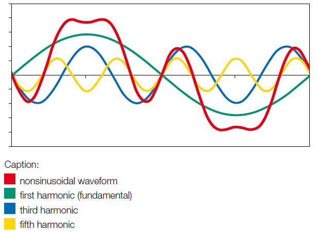
So here is a random picture I stole from the interwebz, showing a very typical sine wave and how harmonics add up to give you something that is not as smooth (the red waveform). This is obviously a little exaggerated.
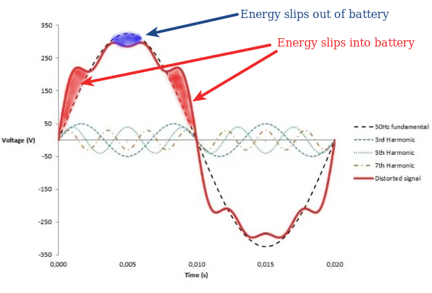
And this is what happens in a bi-directional system where the battery is essentially in parallel with the grid. Again, a borrowed image I coloured in a bit.
That adds all sorts of extra problems for a control loop, which must control the voltage of a battery while it’s expecting a sinusiodal waveform, and not getting it. This is one of the reasons why, in some systems with highly charged lithium batteries, it will sometimes simply go overvoltage. It is the nature of the beast.
Please tell me more. The above is how I understand a particular issue that shows up occasionally, and I was made to understand it has to do with the voltage and how the waveform looks.
Well, this is at the edge of my knowledge of the subject as well. But what I know is that when you are connected to the grid, you should act as a current source with unity PF (within a small margin). Think in terms of a boost converter, where you are charging an inductor with current, and then it becomes a current source. Without a cap to filter, the voltage will spike to infinity (for an ideal inductor and no load). This is what you want when grid-connected and exporting/grid-tied and supplementing the grid. It does mean that the battery load has a decent 100Hz component on the current (I assume this is what is referred to as DC ripple in Victron terms?). When energy is flowing from the grid to the battery, the work mode is different, but you are essentially then a current source to the battery (while also maintaining power factor, which also results in DC ripple on the battery).
When there is no grid, you want to be a voltage source, so you change the control algorithm a bit - you are technically still a current source, but your feedback loop uses voltage as control.
This is with reference to what I assume the Victron topology looks like, from bits of information I could gather. There are other topologies that I have an even more frail grasp of - so they might work somewhat different.
It’s an LF design. The transformer is connected to the grid and the low voltage side is switched with a 20Khz PWM-controlled signal that forms a sine wave, locked to the grid frequency. This is also where my knowledge lacks a bit. There are (to my knowledge) two ways to make energy flow in one direction or the other.
The one is to make the generated sine wave lead or lag, which will cause current to flow in the relevant direction.
The other is to adjust your PWM ratios so that you pull the voltage down (causing current to flow inwards) or push it up (causing it to flow outwards).
In practice, those two are probably the same
However you do it, I suspect that whenever the sine wave you’re pushing into/pulling out of doesn’t match the current PWM ratio you are using, then you don’t quite get what you want.
I also need to add that things differ when you are actively feeding in higher levels of energy, vs when you’re around the zero point with a full battery and you’re just trying to hold it there.
The Victron design has a modified transformer, where one of the windings is only wound on about half of the torus. This increases leakage inductance a lot and means the transformer acts more like a transformer with an inductor in series on the low voltage side.