What would you do if this was your option?

Right, after a LOT of backwards-forward-sideways decisions, talking to quite a few people (engineers too) in and around this batteries inside homes, and what the new regulations willl entail if one does it today, added things like roof structure confirmation and fire certificate or whatnot, I have made up my mind.

Note:
Lifepo4 is safe, very safe.
If you monitor it, maintenance checks, very VERY safe.

BUT …
If a Lifepo4 battery has a “heated temper tantrum”, the reaction is unstoppable.
Understand that.

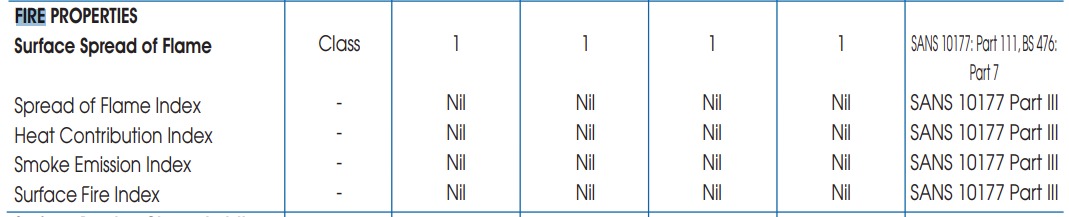
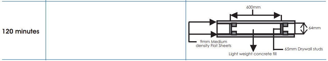
Now, if one wants the batt inside the house today, the regulations apparently are “out there”, not yet official (presume lots of heated (pun intended) debates going on), you would need a 120minute Fire Resistant battery case, with a max limit, if memory serves, 10kWh(?) or such.

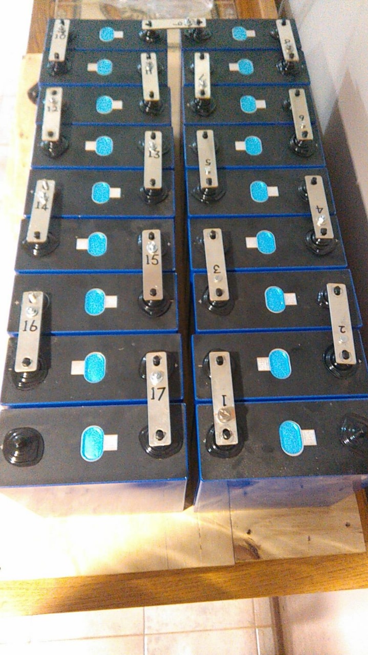
17kWh like I have, nope, not allowed.

Looking at it all, my view, 120min Firer Resistant battery case, that is a “band-aid”. Straw grabbing.
Why?
The gasses released. They can kill you.
But far worse than that, and this is the other “thing” with lifepo4 batteries, ventilation.
The gasses can build up and that is where I deduced, the truly dramatic issue is, with the ongoing “heated temper tantrum”.

That vid of the fireman walking away from the closed garage door, next moment him ducking as the door barely missis his head coming past him is stuck in my mind.

So, that is some background.

In the garage, the boards are up.
Suzy is parked there.

Inverter left, batteries in the corner, Combiner box and MPPT’s right.
Wall on the right, AC DB.
Thinking of the Lynx above the batteries.
Keto Fuse, my emergency disconnect, still working that one out if the car is parked.

O, and it is silicone cables all the way.
Batts to inverter is 75mm2 silicone.
250 MPPT is 35mm2.
… ek willlie meer sukkel nie.

Some may call out, exasperated, Wooden boards!?
Yes, it is allowed. Some suppliers cover wood with a thin metal plate calling it “regulation”.
Wood starts burning at wot, 200-300deg C, how is a thin metal plate over wood going to mitigate that?

It hit me too, I want wood backing (less holes in the wall too), IF the equipment does “light up”, falling off the walls increases the distance from the concrete slab above. :slight_smile:

And because I was gatvol of connecting balancing harnesses, removed the guesswork.


“Nou weet ek wat hulle weet.”

System is now waiting for Jaco to come and re-mount it, move the 5 strings from the back to the front to connect to the Combiner box in the garage AND then the electrical work.

I’m moving the entire Critical Loads Circuit feeding 3 x DB’s, to the garage. One point of control “julle bliksims”. In the words of Achmed “I keel you” power.

1 Like

O, and the goggas … very fine sieve over the inverters intake/outlet.
All tiny parts and connectors, will have to seal them somehow to mitigate corrosion over time.
The batts cover … busy finding a supplier. Can cost a kidney if you don’t shop right.

Also contemplating doing this … that I can swap BMS’es quickly.

And I want to get to this too … to get away from the top of the battery. Just a tiny TTT safety feature request.

If I bend busbars, they look k…k. WIP.

I recognise those pics from somewhere - can’t remember where…?

Help us please… :wink:

Andy from Off Grid Garage … his first 3 x 280ah banks he built.

Ah. I knew that but was hinting at a “reference link” under the images … ie to the Youtube video :wink:

Me trying to keep potential legal wolves off the front “stoep”.

1 Like

Check the manual of the equipment. For example, you are not allowed to install a Multi-RS on wood. It is in the manual. So “allowed” might be a term that’s subject to certain caveats.

Thanks for that heads-up - it is one of those teeny titbits that are rather crucual.

My case, I’m old tech. Mulitplus 5kva.
And why I need 80v fuses, and not 58v fuses due to the 18 cell bank … and therefor cannot ever use a Multi-RS on this bank.

Read somewhere the other week, don’t mount anything on wood that has a heatsink at the back … just don’t.

Now someone may point out, TTT, your MPPT’s … my reply, fan boet, fan.
They work damn hard and I see absolutely no need for them to run that hot, even if they can.

Ps. And if I get exasperated myself, 9mm Nutec board over that wood.

You have to spec the thing for fault conditions. I have a rather nasty picture from a friend of an MPPT that suffered some kind of catastrophic failure around its screw terminals… and it would have set a wood backing on fire. There is no doubt of that.

I’d go with that Nutec board straight off the cuff. Even straight on the wall would probably be safer.

As far as I know the Multiplus-II can be mounted on wood, although the manual also states that concrete or masonry is preferred (due to the weight mostly). Page 11 of the manual.

The manual for the MPPTs clearly states:

Mount the solar charger vertically on a non-flammable substrate, with the electrical terminals facing downwards.

In the manual for the RS it goes even further:

c) The Multi RS Solar must be installed on a non-flammable surface and the
construction materials surrounding the installation should also be non-flammable.

I’m really really sorry to crap on your parade… but rather I do it now than later.

Edit: And to be clear, the reason I’m a bit stricter about this and less gung ho than usual… well… apparently there has been some incidents with people not reading the manual. Some manuals were actually changed to make it even clearer.

No crapping whatsoever … I put these things on forums for feedback, and for others to get ideas, and the “do not do this”.

You convinced me. Nutec on behind the MPPT’s and inverter.
Actually have spare (could not throw it away) from the last build.
Easy as chips to mount on the boards.

Titbit:
You want a 120minute fire rated “battery cabinet”, use 9mm Nutec inside, outside fitted to a metal frame, pour light concrete inside, sorted.


From here:

… then one needs to figure the ventilation out, cause 'band aid" to contain the flames when the gasses can explode.

In chatting to someone, let me sum up why this is going outside …

I reached the conclusion, to pay for all that may be “thought up” to cover the ones who give a CoC for a solar system, and battery/ies being inside, with all the latest actual, and potential new regs, it is simply cheaper to move the whole shebang to the garage and be done.

Garages are built to spec already for i.e. a vehicle burning.

The size of the battery bank, being lithium, that also complicates matters immensely.

And then I have the complication, gas bottles other side of the garage, outside, gas line going through the garage, ceiling mounted, to here, again outside the garage, the gas geyser.

Door there goes to the garage.

In talks with the gas installer about getting the AC and DC wires over/past that gas line.
150mm separation required … but what if it is in conduit, not trunking?


Cause there are quite strict rules about wires, circuit breakers and all that around gas.
Apparently, having the inverter on the inside of the garage is fine.
Then the 5m separation is not required.

Gas lines inside the garage, under the slab, the slightly yellow pipe.
This install, CoC’ed, made me question the “rules”, hence the conduit question to them.

The busbars, small hole drilled on the side where the balancing lead would have been connected, self tapping screw to get the thread then this little nifty contraption to fasten the balancing leads to the busbar, for quick connection, removal.

Previously had to loosen the nut on the battery to remove the balancing lead.
Made swapping BMS a rather big task.

Th’s something you do often? :slight_smile:

1 Like

Yes, it actually is.

The strikes to date:
Strike 1 - crap BMS that destroyed the first bank, so I got a new JBD BMS and cells.
Balancing harness had to change.
Strike 2 - then got an new import with upgraded JBD BMS’es.
Balancing harness had to change again.
Strike 3 - the one that “broke the camels back” - had an issue with the newer JBD BMS - upgraded the firmware with Chinese “help” - had to remove that BMS and revert back to the previous version BMS, the then spare BMS.
Balancing harness had to change again.

Got a JK BMS now, and the balancing harness has to change … again.

More important, a better than the JK BMS comes out in a few years, I want to swap it out chop chop, planning for a balancing harness to change again.

For me, BMS’es are but a electronic part of the system, like an MPPT, Cerbo, inverter … fuse.
Won’t last the lifetime of a lifepo4 bank either.

So make BMS swapping KISS and TTT safe to swap them out quickly.
Just like i.e. changing a fuse. :+1:

This is the ultimate quick change of a BMS - will get there, thanks to Andy from Off Grid Garage.

Sounds to me like you need to wire in one of those multipin automotive plugs for easy swapping. Maybe a Deutsch connector or two (popular with electronic hobbyists and car people).

Open to ideas.

Looked at the Deutsch connectors briefly a while back.

That pic above, the most simplistic DIY (for me) for 15-18 cells balancing harness connection to the BMS.

The black wires, 2mm silicone wires with properly crimped lugs.

On the JBD BMS’es, the 20-24S ranges, this is how you wire the extra leads not used:

The JK BMS, the wires not needed, cut them off or make them safe:

Deutsch connectors are awesome and will be ideal for this application, I use round 9 pin ones rated for 24v on my antenna rotator, but you get them up to 24 pin if I remember, the ones I use is even IP68 rated.
RS components is your friend.

1 Like

Well, honestly, if you swap back and forth, a connector makes sense. For someone in R & D who works with multiple BMSes on the same set of cells (due to space or cost reasons), plugs would make sense.

In your case it seems you only swap forward. So push-in pins (and a good bootlace crimper) is probably the way to do.

1 Like