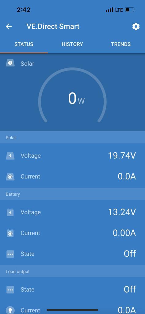
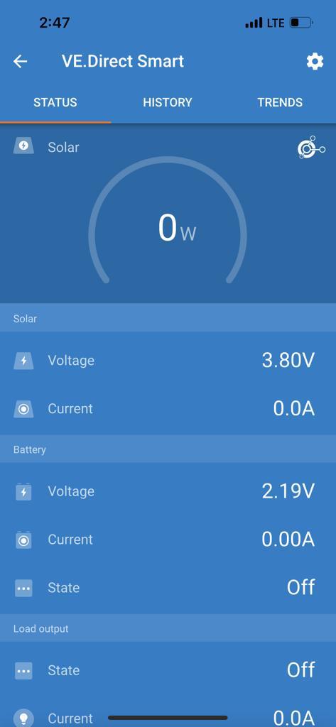
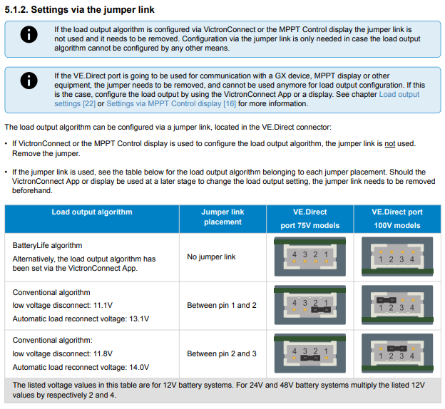
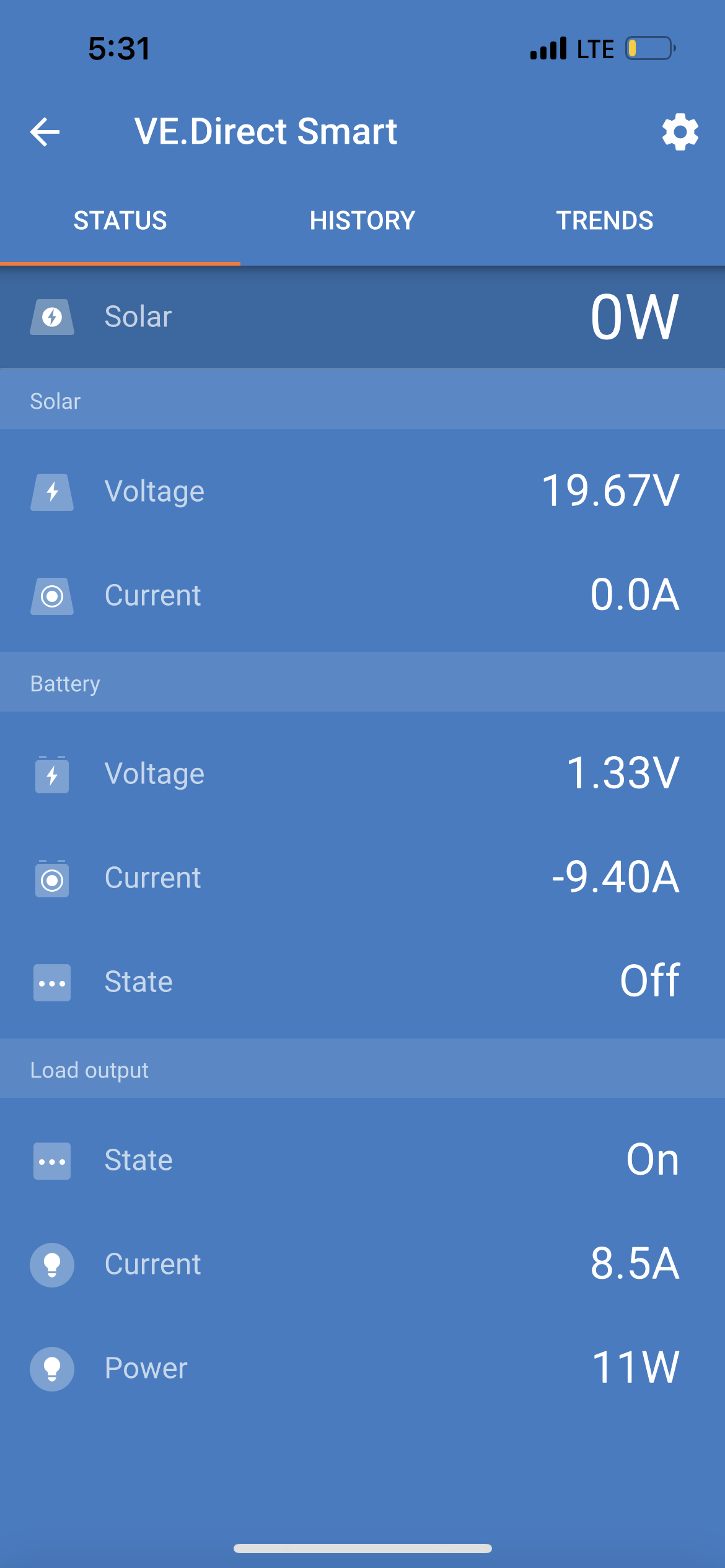
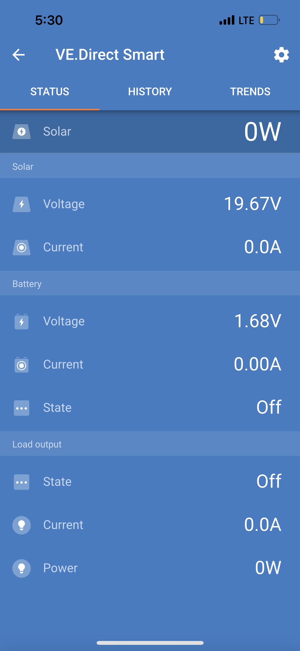
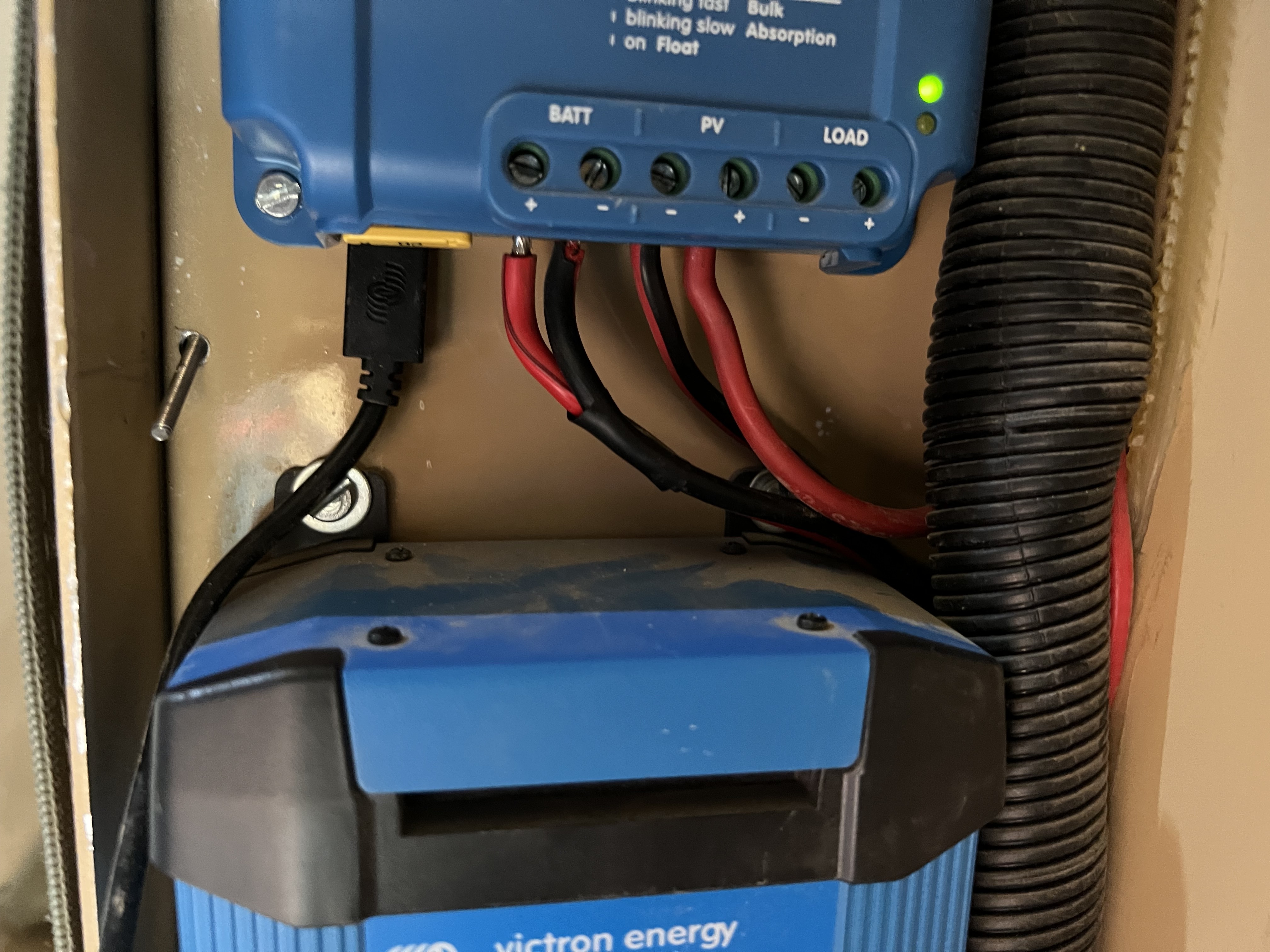
Hey everyone, I’m new here. I was specifically recommended to come here via a fellow club member at 4x4community.co.za. My fellow club member, Jaco, was trying to help me diagnose and issue I’ve been having with my mppt charge controller. I upgraded all my caravan electronics (12v system) earlier in the year, and didn’t realize until I added the Bluetooth dongle to the mppt, that the roof mounted solar panel wasn’t charging the batteries. I have constant voltage at the 2 x 10⁸ah Blue nova lithium ion batteries, which charge just fine on the victron dc-dc or bluesmart 220v charger. The BMV reflects a very similar voltage to the batts, and even to the MPPT battery terminals. The PV panel wires are reflecting 19.2v at the mppt posts and all is wired correctly. The mppt 20 amp fuse was missing upon installation, but after I added it, nothing changed. The app reads 19.74v at the panel and 13.24v for the battery. It then fluctuates and changes to 3.8v at the panel and 2.19v at the battery. Jaco recommended I come here and specifically ask for @plonkster and/or @JacoDeJongh to weigh in.
I live in Namibe, Angola, and the nearest victron supplier would be in Windhoek, a 2 days drive for me. I’d appreciate any help or thoughts.
First thing: Did you ground the negative of the panels? If you did… well, undo it. This being a 75/15 (older platform), I think the hall sensor that measures the current is in the negative line. When the negative of the panels and the negative of the battery are both tied to the chassis, it short-circuits the current sensor and one of two things happen… it doesn’t work… or something blows up.
If that is okay: disconnect the battery and check that the MPPT can make a steady 13.5V or 14.2V on its output. You could even try connecting a 12V lamp to see if it will power it. In other words, use it like a 12V power supply.
Measure the PV panel voltage while it drives a load on the output side. Normally, with a 36-cell panel (which is almost certainly what you have), you expect around 21V on the input side when it has no load, and around 18V when operating at full power.
Reason I ask all these: It is also possible that the MPPT is simply broken.
Always nice to help someone from up North. I’m a born Namibian. Lived in Windhoek the first 20 years of my life. Sometimes think I should go back. The people are friendlier
Thank you for weighing in. In regards to whether the PV negative wire is grounded or not, I’ll have to go check as I paid Bushwackers to do the install.
Would I be able to disconnect the battery wire from the MPPT and do your test by putting appropriate wires into the ‘load’ part of the mppt and trying to power something like a 12v fan off of it?
Normally this will not work. The load output is only on if the setup allows it to be on and only over a certain voltage. Rather connect your load to the battery port after you disconnect the battery wires.
Try to keep the load below 4 amps, 12x4=28 watt roughly.
I also suspect that the someting in the MPPT is gone and when it starts to charge at higher currents something internally causes a short that will pull the voltage down…
I know you were really busy today and might have missed this. Looking at Jaco’s picture above, the load output was off in both instances… I dont think its configured.
Okay, I need to understand this correctly, Even during the test and the app showing the low voltage, the battery voltage remains at 12 volt plus and the panel at above 18 volts?
If that is the case, I am 99% sure the issue is with the MPPT.
Please forgive me for asking something this simple. Are you sure the fuse are correctly installed and not blown?
I have seen some of these fuses where one leg is making contact and the other one not.
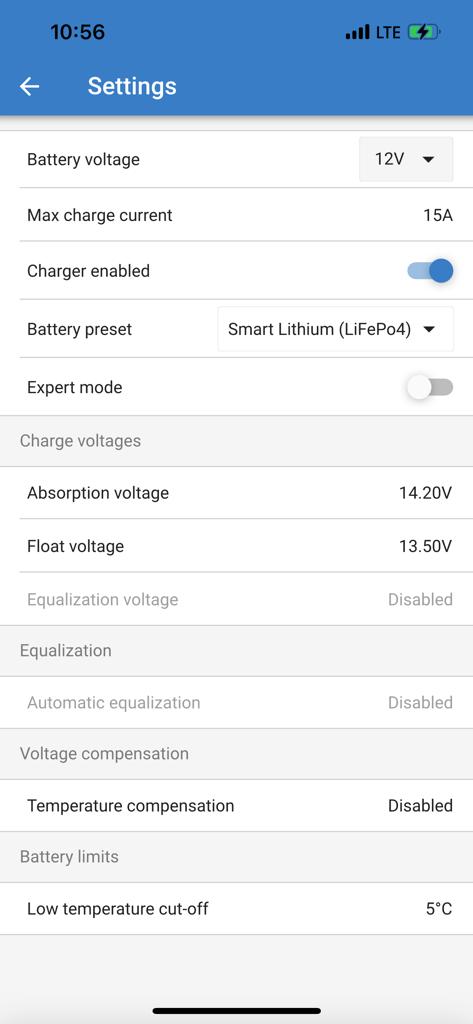
Gentlemen, thank you SO MUCH for weighing in. @JacoDeJongh, sir, you are correct in much not being configured. When I received the van back, hardware was installed (save the 20 amp fuse), but nothing was configured, and I was none the wiser. Later I began to figure these things out a bit at a time. How should I configure the load output?
I pulled the fuse to double check, and the bridge is still good. It’s not a transparent fuse, so there could be an issue, though it is a new one. I do have 2 spares which I’ll try.
As a side note, I pulled the batt wires, plugged in load wires and had nothing. They wouldn’t power up the LED lights. The app readings went really awry with that.
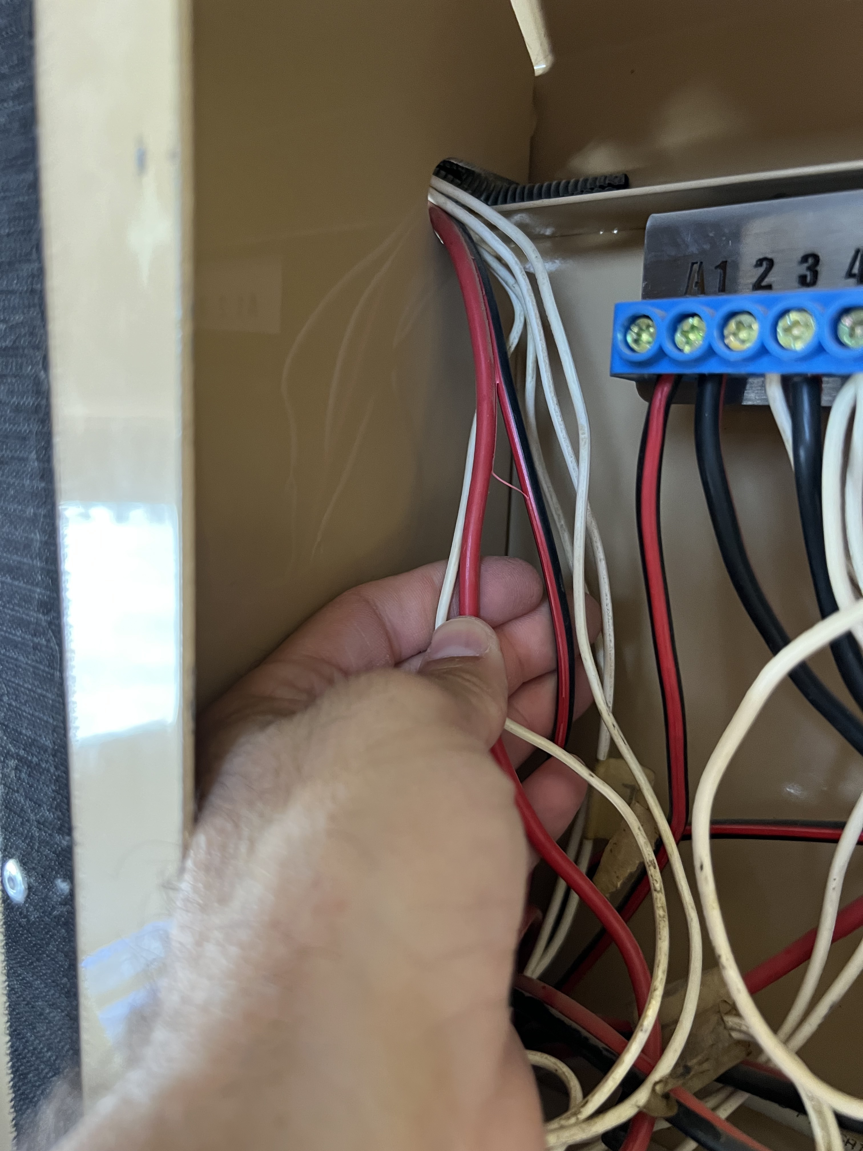
In this first image above, I’m holding the positive and negative wires coming from the PV panel. PV panel positive goes to the solar breaker as seen in the image below.
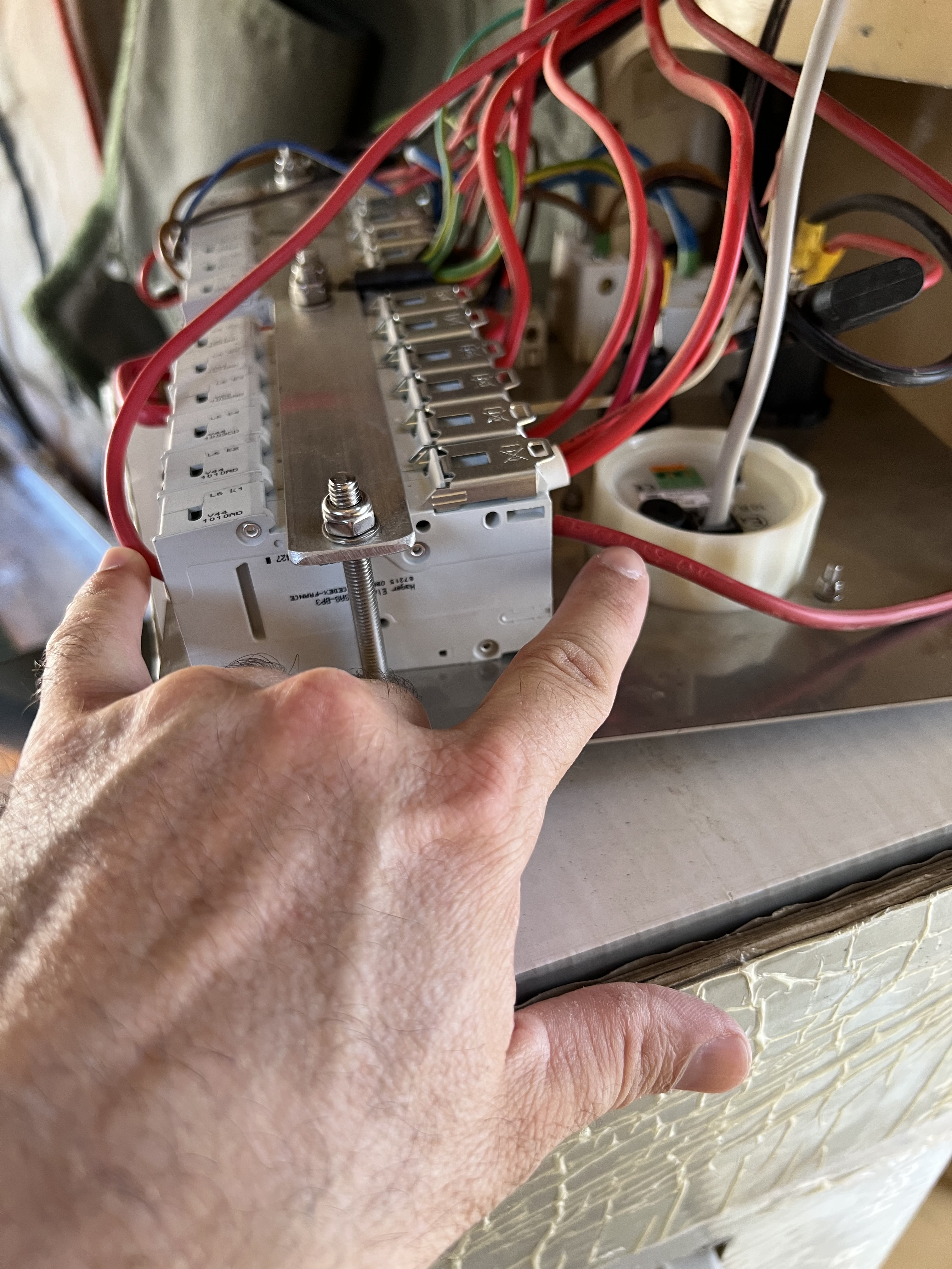
In the image above, the positive wire on the left side of the image comes from the PV panel into the breaker, and then leaves on the right side of the image and goes to the positive MPPT post.
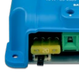
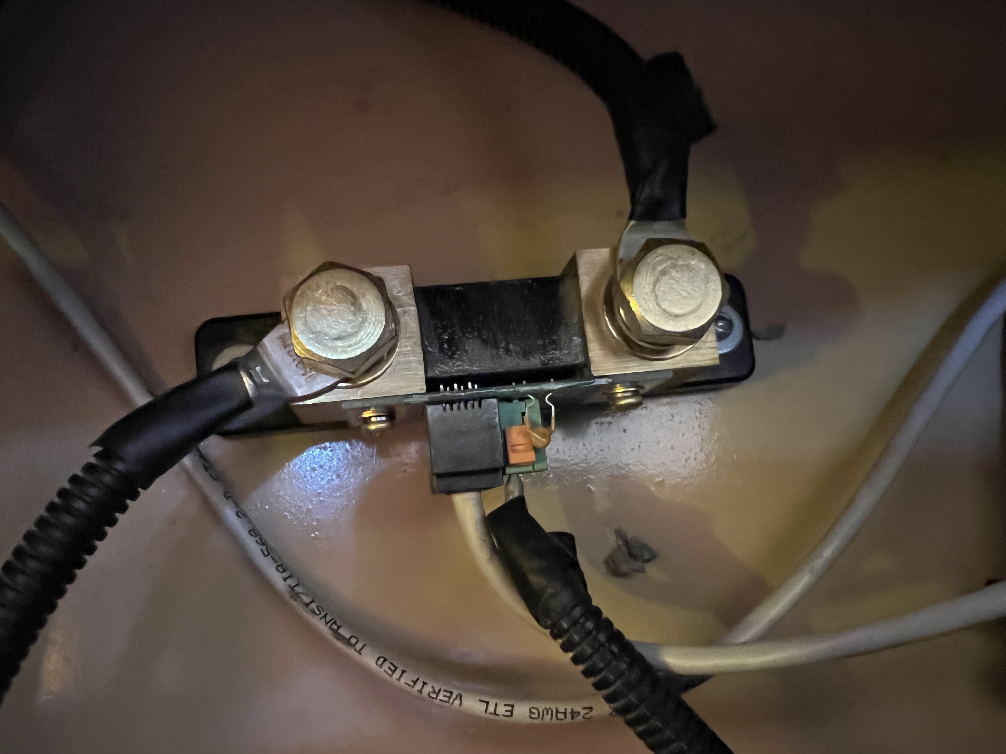
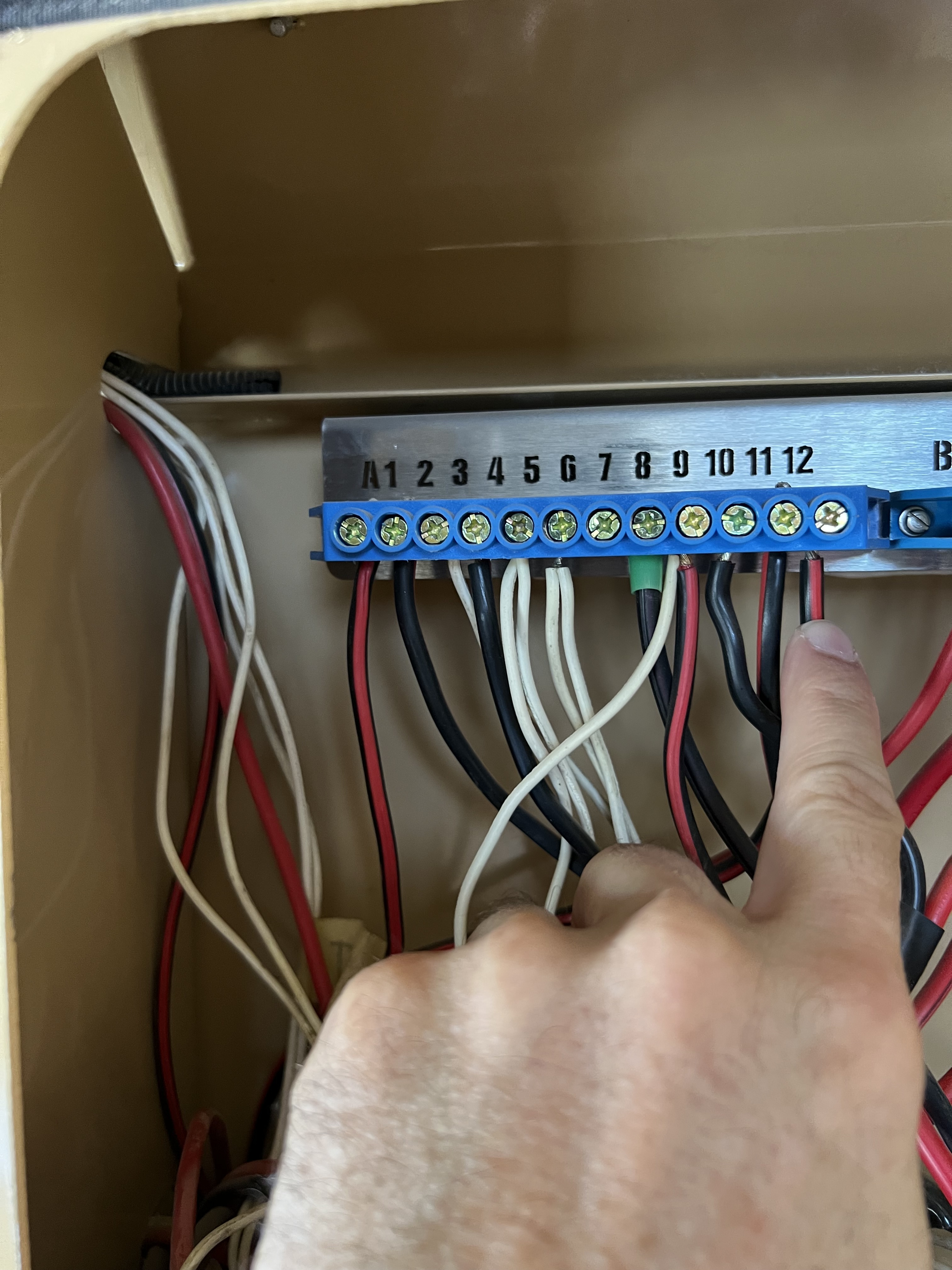
In the image above, is what I believe is a shunt. The bolt on the left goes to the battery negative terminal. The post on the right, goes up behind the fuse panel, to a plastic line of steel screws/bolts that secure many wires, and it’s numbered A12, as can be seen below.
From what I can see, the batts are likely grounded, but it seems as though the PV panel isn’t.
Furthermore, I’ve done the test suggested, by putting wires into the batt pós/neg post at the mppt, connecting it to a light and seeing what happens. I tried that and the wires only read between 1.2-2.3v and never came close to making the LED light even flicker. PV panel was pulling 20.3v in the sun at the MPPT posts.
Thanks for the response. The mppt is only just a year or so old. Do you all know what the warranty time frame and procedures are? I’m quite shocked as I don’t believe it’s ever worked…