This afternoon (and it has happened before) I had some strange behavior from my 150/35 MPPT.
Its West facing so I would expect some solid output through out the afternoon. I have a good load and batteries are almost full or full.
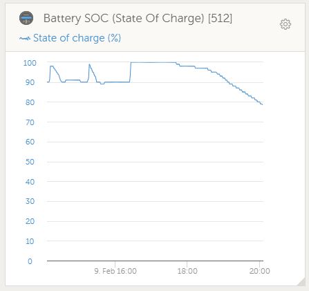
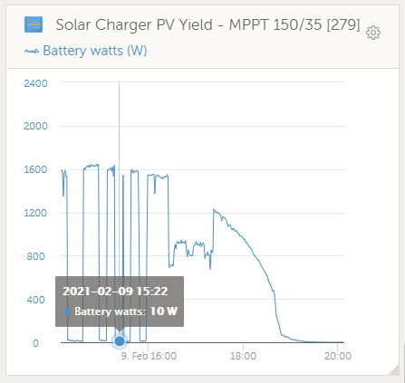
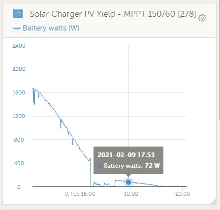
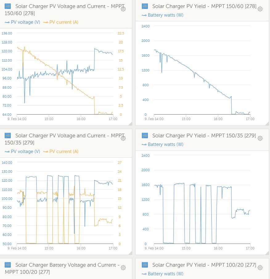
My NEast MPPT (150/60) slowly ramped down as you would expect but the West MPPT150 (150/35) went from Max to 0 a few times at regular intervals (see graph). I would expect it to also ramp down like the other.
I also noticed that when it drops off to 0 the battery draw increases to take up the slack… The MPPT then jumps back to 100% after almost a set time and the battery then gets charged back to 100%.
Could this be a temperature issue with the MPPT? Can’t measure that as its not available on the Cerbo.
ESS and DVCC is enabled.
Latest MPPT Firmware
Latest GX Firmware
The battery watts will go to 0 if your load matches your solar output and therefore will not charge the batteries. Looking at the graph it could be a stove/element switching on at intervals to keep the temperature.
Thanks @Paul.
But none of that on at those times… it also takes a long while for the MPPT to respond to the battery drain… 10mins plus or about 10% SOC.
The other 2 MPPT’s have a nice even charge current unlike the 150/35. (see the 150/60 graph).
OK - think I may have the issue…Lets say NON-issue
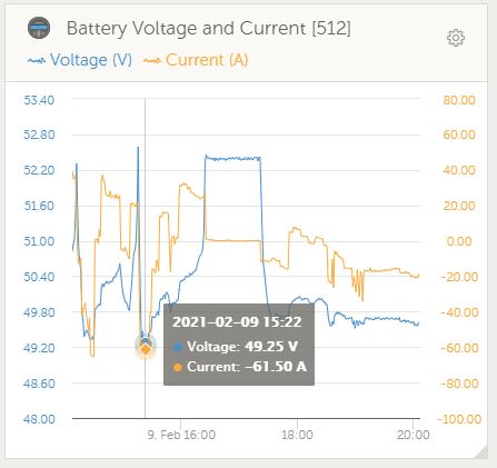
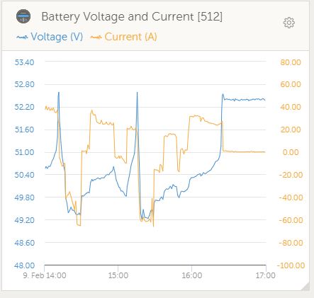
Victron voltage cap for Pylontech is 52.4 (see the drop off at around this voltage above…
Looks like this is the issue per the online FAQ.
I also think the 90-100% range for SOC is so fluid the GX waits for a while to “reconnect” the MPPT to lift the SOC back… nice and clever (to avoid more spikes).
My MPPT’s are eternally managed by the GX and its choosing the MPPT with the highest output as its focus… (clever or coincidence @plonkster ?).
Those must be working well when they are eternally managed
I also have 2 MPPTs that are managed by the GX and when it needs to limit the solar input cause the battery is full one MPPT will be limited more than the other. It seems that the one that has(or had) the most solar production will be used to try and match the load while the other one is kept lower (or idle).
Thanks @Louisvdw - Mine seems to be the MPPT that has the most production at the time… ie West in the afternoon. @plonkster may be able to help us with the rules DVCC uses as the voltage closes in on max…
The external control really means only one thing: Something else in the system (either the BMS, or the Multi) determines the charge voltage, and the solar chargers are told to follow.
If there is a charge current limit, that too is split up between the MPPTs, and there is an algorithm that I literally based on the biblical parable of the talents: Solar chargers that do well are given a higher limit, those who do poorly have theirs taken away.
So that is what I would look at. Possible, there is a current limit involved and the 150/35 is on the loosing end.
Could be other things too. But generally, the MPPTs only look at the voltage. If they are told to aim for 52.4V, and the battery voltage is less than that, it should start up within seconds… not minutes.
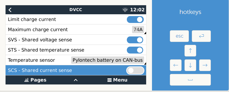
Should SCS be on as well…?
Default is OFF based on the fact that the Battery is in control… am I correct in my thinking?
When I switch it on the Status changes to Disabled (External Control)
SVS often cause more problems than it is worth. In a self-consumption system it adds nothing. What it does is attempt to compensate for calibration and cable losses, so that the Multi, solar chargers and battery agree on the voltage (which is needed when you’re feeding excess PV into the grid, and so forth). It often causes problems because the voltage readings you get from the BMS is only every few seconds, and is often stale by the time you get them.
STS shares the temperature of the battery with other interested parties (so they can do temperature comnpensation). Does nothing with a CAN-bus battery, since the battery already controls the voltage, so temperature compensation is not done in any case.
SCS writes the battery current BACK to the solar chargers, so that they can do better tail-current detection (ie determine when to go to float). Again, this does nothing when the BMS already in charge of the voltage.
No need. The battery already sends that same value. If you also set one on the GX device, then the system will use the LESSER of the two, so this is useful only if for whatever reason you need to set a lower value. Otherwise turn it off.
And one more thing, just to complete the whole “thought”. In an ESS system, the Multi and the Solar Chargers always sync their voltage measurements to compensate for calibration and cable losses. When you turn on SVS, all it does is bring the Battery to the party as well… which also often introduces instability in the loop because of the inherent slowness of the BMS readings.
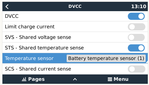
So just to make 100% sure. DVCC is still ON in this case, yes?
With my driver I do implement Charge limits on the upper/lower edges of the SOC as I found if I don’t do it and the driver just report values that the MPPTs go at full blast up even at 99% and there is no DVCC current curve as I expected. I guess the battery BMS override this as well?
Yup. DVCC merely means the battery calls the shots (distributed voltage and current control). There are several additional DVCC-specific options (such as SVS, etc) but even if you turn them off the basics still work.
Yup, that is LiFePO4 for you. Accept full charge all the way. Some batteries will drop the charge voltage to make sure there is no overshoot, and leave the charge current alone. Some reduce the charge current. And some set the charge current limit to zero.
A CCL=0 does not work well for a system with DC-coupled PV. Because that means: Please adjust the limits on the solar chargers so that it matches the load… and as you know… the loads are never static, they fluctuate all over the place. So you play this game of catch-up (like a donkey cart, only in the track when it’s going across it), and little bits of charge go in and out… until the battery overvolts…
Yes, that is currently my daily routine. Overvolts from around 2pm when the battery is trying to play the buffer but can do not more. This is after all the dishes has been washed, geyser heated, water pump pumped and I wish I had more stuff in the house that needed power.
Would have been wonderful if there was someone that needed extra power every afternoon with a reasonable cost structure. Hmm.
PS. That someone has implemented loadshedding from 1pm today…