When load shedding ended at 2am this morning (these things always happen at 2am, don’t they?) my Multiplus II GX crashed. After turning it off and on again, it booted up fine and all was well.
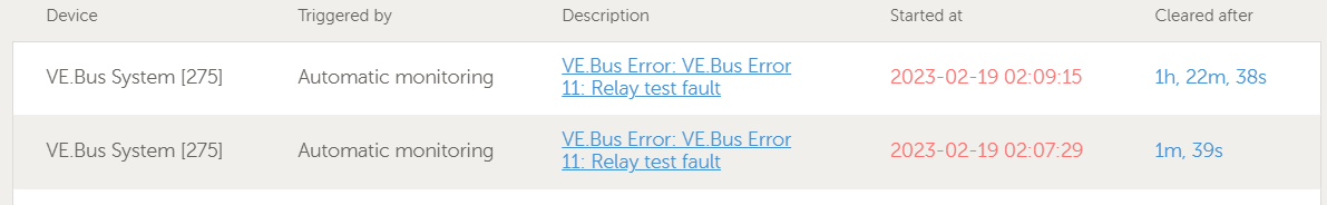
Digging into the logs this morning:
Firmware version: 497
I have 3 Mutlis in parallel, with the GX in charge.
Next loadshedding is 4pm this evening, and I’ll update this post then with what happens; just checking if this is something I should be concerned about?
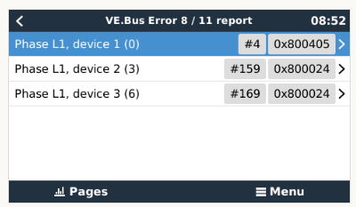
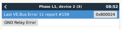
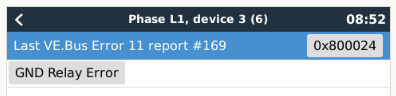
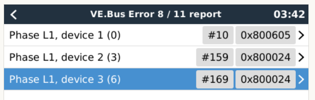
It looks like the complainer is the master (device 1). The other two simply says “something went wrong” (the 4 at the end), and it involves the ground relay (the 2 second from the right).
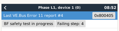
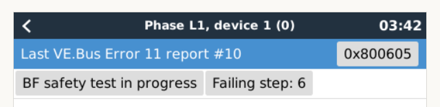
The phase master is saying “test in progress” (1) and “something went wrong” (4), which makes the total of 5. The 4 next to it says “step 4”.
The bits that normally indicate which test failed (was it open when it should have been closed, or closed when it should have been open?) are not set.
One possibility, a wide grid voltage fluctuation occurred at exactly that point in time. Just a theory, but because the older Multiplus-II uses a voltage measurement to check the bonding relay, and step 4 involves checking that a particular voltage measures >100V… that sounds plausible.
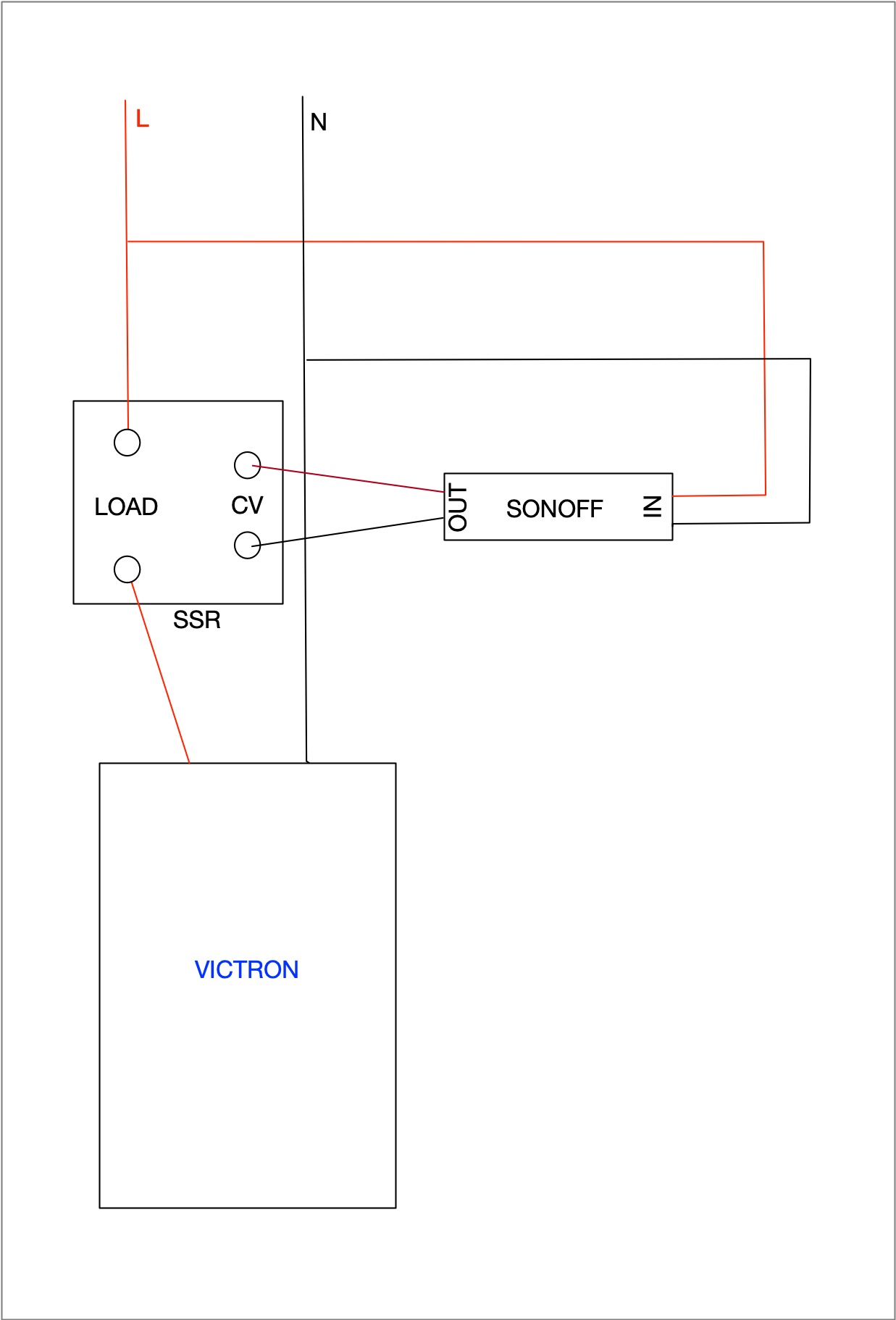
Because of the voltage fluctuations and other nonsense during end of load shedding (first couple of minutes), I put the input into my inverter over a 60A SSR (its an overkill but ).
SSR is powered by a tasmotized sonoff switch (that gets the power from the very same line) that is configured to go “on” 5 minutes after power is restored.
This is basically just a 5min buffer allowing the electricity network to stabilise. Also, gives instant notification when grid is lost or restored via HA.
Maybe something you can look at, but you would I think need three SSR (one Sonoff would suffice)…
What I’ve learned about this type of error … as with every blerrie thing … I will get it the “other way” round, as in when LS starts, and only early mornings.
You at least got it the well-documented way i.e. when LS is over.
His test is the opposite of yours (in some ways), but also weird in that it didn’t end in a definite diagnosis (that the relay was open or closed). It ended sort of in the middle, with something that is wrong, but not pinpointing the specific cause. Which is another reason I think it was grid weirdness.
Weird thing is, when turning them back on (only at 3am when I woke up and realised there was no power), it tripped immediately, then recovered on rebooting itself (ie with no action by myself)
I did a bit of digging through the (long) history of my WhatsApp chats with @JacoDeJongh and found what I thought was there: I’ve seen this error before, a year ago. Eventually that MP GX had to be replaced under warranty. I’m hoping this isn’t a similar situation…
Edit/update: tripped again at 10am this morning, again error 11 at step 6.
For now, the workaround that worked yesterday evening is to manually trip the inverter input breaker myself, and then only put it up at least 10 mins after load shedding ends.
Also means, if I keep my batteries full enough, that I can trip it before I go to bed, and not have it trip at 2am when load shedding ends.
Currently being loadshed until 10am, with the input breaker down. Will see how it behaves at 10:10am when I put it up…
Maybe I’m a little fast on that assessment. The obvious things to do, check that the inverters are all properly earthed (I’ve seen errors due to poor earthing), get your earth impedance checked by a sparky, check the TN bond (0V between earth and neutral on the supply side), and so on and so forth.
I’ll ask around a bit so I can better understand what the errors mean. I mean, I have a memo saying which step corresponds with what relay, but I don’t know where those relays are.
Interestingly, step 6 is also a “voltage too high” measurement.
OK, this is roughly the layout of the transfer switch:
L ------------- K1 ----+-------- K2 ----
                       |
AC-in            (measure here)          Inverter+Critical loads
                       |
N ------------- K3 ----+-------- K4 ----
K1 and K3 work together as a pair, and K2 and K4 is the second line of defence. You must have the two individual pairs for redundancy, required by grid code(s).
As I understand it, the test is done by measuring the voltage “in the middle”. If you close only one relay at a time, there should be no voltage measured in the middle. If you close either pair, you will see a voltage (either from the grid, or the inverter).
Now: An error at step 6 means that a voltage of over 100V was detected while only K1 was closed (there should be nothing there, because K3 is open).
An error at step 4 means a voltage of over 100V was detected while only K2 was closed.
When it failed on step 6, it also indicated that it was testing the ground relay. That points at K4 a little harder.
This may be a legit problem, but I’m totally guessing. A repair center will probably know better than I do.
For reference, this is what happens. It works backards from step 8.
Step 8: Close K3 only, check that there is no voltage detected.
Step 7: Close K1 (and keep K3 closed), check that a good voltage is detected (over 170V).
Step 6: Open K3, so only K1 is closed. Check that no voltage detected. Then open K1.
Step 5: Close K4. Check that no voltage detected.
Step 4: Open K4, Close K2. Check that no voltage detected.
Step 3: Close K4 (keep K2 closed). Check that a good voltage is detected.
Step 2: Open K2 (keep K4 closed) repeat step 5.
Step 1: Finalise (will never fail here)
Step 0: Normal operation.
The reason for the double work in the second half, is because the bonding relay is also tested along with one of those steps, but I am unsure exactly when. Remember that when the bonding relay is closed, inverter and grid neutral are tied to the same earth (and therefore together), so a failure in either K3 or K4 can show up in the “other half” of the test.
Edit, November 2023: Turns out the test sequence is different for the newer models that uses the auxiliary contact on the bonding relay, so keep that in mind, the above does not apply to all models.