The "Carlo Gavazzi ET112" explained

Good day citizens of the dark-side.

So in a few posts I’ve made on this forum many have advised I get an ET112, for measurement, for controlling/optimising ESS, for getting more out of my PV, etc.

I have tried to make a study of what this device will actually do and yet still find myself without a clear understanding. I’ve read spec sheets, hardly understood, comments on Powerforum give some clue, but a beginner’s guide, or intro, typically an “Explained” post/article I cannot find.

I won’t waste your time with my assumptions. Also, sorry, I may seem lazy to you, but I’m not really technically educated/informed and find reading incomprehensible manual after manual, Googling terminology many take for granted very frustrating for I just don’t have that much surplus time.

(in simple terms, feel free to use metaphor too, love metaphor)
Could someone please explain to me what this device does?
Why is it considered so useful in getting more out of my PV?
How does it enhance, or aid in optimising, with ESS?

Threads where it was recommended to me:

Thanks.
c.

This device is a simple energy meter. It tells the system what the power usage of the rest of the house is. Without it, your inverter only sees the load after it. If you can measure what is happening between the incoming grid and any other non-essential loads you have, you know what you can export to your house without actually exporting to the grid.

As an example: say you have 100W load on the output of your inverter. It can easily power that with your PV when the sun is shining. Now you switch on the kettle(say 1000W), but that is connected to the non-essential side, before your inverter. If you don’t have the ET112, the inverter is unaware of the kettle, but with it it knows it can push back 1000W to the grid side of the inverter.

What that means is that as long as there is grid, you can use the power from your PV array to power loads that are not connected to the output of the inverter, as long as they are between the inverter and the ET112.

4 Likes

Edit: Clearly I’m typing too slowly :slight_smile:

When you have solar panels, your goal is to use them as much as possible. The more power you get from them, the faster you recover the capital expenditure. The best way to do this is to always run them at full tilt, and the simplest way to do that is to push power back into the grid, while getting paid per kwh.

If you can’t do that due to policy issues, import issues, or whatever, your 2nd-best option is to keep your import at zero, i.e. you try to never draw power from the grid, and never push back. You self-consume the power you produce.

So ESS (depending on mode) typically uses power from the solar panels to keep your import and export at zero: first powering the loads, then sending excess power to the batteries, then scaling down solar production. Again depending on the mode, it can use power from the batteries to power the loads, making sure import is at zero above all else (excepting the exceptions, such min SOC, etc.).

To be able to do that, you need a clear picture of what is happening at the grid connection point. You need to accurately see what is happening at that point that you’re trying to keep zero.

Now the Multiplus II has a meter built in, but it has two problems:

  1. It is not a particularly precise measuring instrument
  2. It is physically inside the MP at the AC input (there is an extension cable with a clamp too…)

#2 gives the most issues: If your whole house is connected to the AC output, then the AC input is actually your grid connection point, but this is almost never true. Even if it were, you’re still stuck with the accuracy of #1.

So the ET112 and friends give you a very accurate meter that you can put where you want. And you want to put it riiiiight next to your main breaker – the grid connection point.

Now the MP can include loads that are not connected to the AC output, but between the grid connection and the AC input in its calculations. So it will push back power from solar or the batteries through its AC input to the loads connected there, but not so much that the power flows into the grid.

Your big consumers such as stoves, geysers, aircons, etc. are all connected here in most cases.

So the ET helps you power those with excess solar and/or batteries to improve the self-consumption, instead of scaling down production.

It makes a bigger difference the smaller your inverter is, since then most big loads are on the “wrong” (input) side of the inverter.

Hope that helps.

4 Likes

OK, the first thing to understand is that the Multi has the ability to install assistants, which is a bit like apps on your cell phone: They allow the inverter to do more things than in its default configuration. One such assistant is the ESS assistant. That is critical to this explanation.

Normally the Multi’s inverter component is switched off when the grid is on. Only the charging part is active. When there is a grid outage, the Multi opens the relay to the grid (called the transfer switch, internally we also call it the backfeed relay for reasons I’m not perfectly clear about), and then it turns on the inverter. In other words, the default setup of the Multi is to work like a UPS.

When you install the ESS assistant, the Multi becomes an AC-coupled inverter. It can close the backfeed relay AND switch the inverter on at the same time, allowing it to feed energy into the grid.

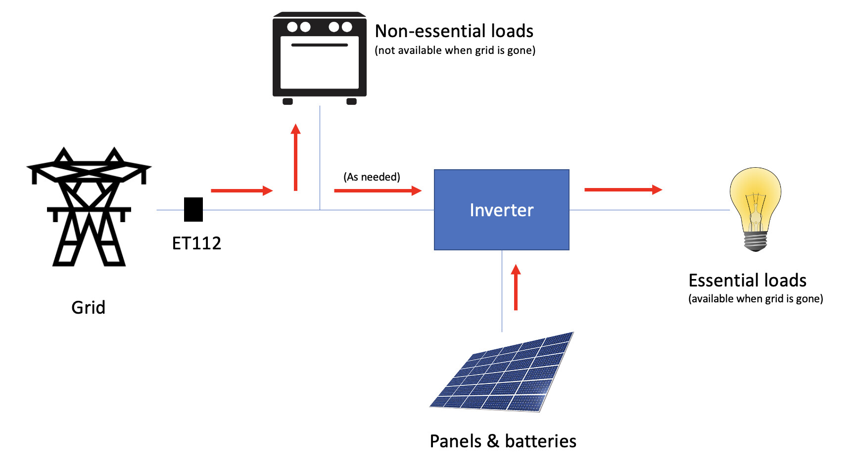
Now if you look at the many pictures of the Multi online, you will see it is always drawn in the shape of a T. The grid is on the left, the backup loads are on the right, and the inverter/battery is at the bottom. There is a switch drawn in the left hand branch of the T (that is the backfeed relay, aka transfer switch). When running ESS, that switch is always closed, so you can think of it not being there.

If you now think of that inverter pushing energy into the top of the T, if it pushes in MORE than is on the right-hand side of that T, the rest is going to flow out into the left branch (towards the grid).

Alright, if you are still with me, now we introduce an energy meter. On that incoming branch of the Multi, there is an energy meter. So the Multi can balance the amount that it feeds in so that nothing flows into the left-hand branch, and only the loads on the output are compensated for. In other words, the “zero point”, the point in the system that the Multi keeps at zero (or rather, at whatever you set ESS setpoint to), is at the input of the Multi.

But… and this is the beauty, if you connect an external energy meter, then you can move the zero-point. Typically you will move the zero-point to the point where the utility connects to your installation, so that the Multi feeds all available power to loads within your installation. And that is where the ET112 comes in. It measures the energy use at a different spot in the installation, and the Multi then zeroes THAT point rather than it’s own input.

The reason why you do this, is twofold. The one is that it allows feeding excess energy to loads that are not on the output, which you don’t WANT on the output because they are too large (swimming pool pumps, geysers, stoves, etc). But it also saves a heap of rewiring.

What I mean by saving rewiring: You could get the same effect without the ET112, by placing your heavy loads on AC-Out-2. The Multi automatically drops AC-Out-2 when the grid fails. But that requires rewiring all those circuits, which may be more expensive than you think when considering things like outside buildings, garages, and the mentioned pool pumps, splitting the DB in some cases, etc etc. At the cost of an ET112, it’s often cheaper to do it that way.

3 Likes

Something else that might help in understanding, is to look at how other grid-tied inverters do the same thing. For example, look at an SMA Sunny Boy combined with their “Home manager”, or a Fronius that can also have an energy meter installed for limiting, or even the popular Solis inverter that has a CT that you clamp to the “zero point”. Same principle.

The Multi is a hybrid inverter that has the capability to do both battery backup and grid feed-in, and as a result it uses the same zero-point solution as these others.

AFAIK the Deye / SunSynk also come with a CT clamp which does exactly the same thing.

It’s perhaps worthwhile to mention that some utility electricity meters do have a problem with feed-in, and the inverter is “technically” feeding back into the grid. Typically when that load disappears (say the 1000W kettle @_a_a_a mentioned) disappears, then the inverter’s 1000w that it was getting from your panels and pushing back into the grid continues for a second or two - and now gets dumped (through the ET112 and your municipality electricity meter) back into to the grid.

Some municipalities’ meters see this as illegal feeding into the grid and might charge you a normal rate for that (even though you’re technically supplying electricity to the grid), some might penalise you a bit more, some ignores it completely (I’m in that position) and some meters even trips (worse case scenario).

One thing to keep in mind is that even without the energy meter, the situation where the kettle switches off and 2kW flows back into the grid for a short period still happens. The duration is just much shorter.

But if you have one of the tripping meters (like some of the conlog meters), they still trip, because their limits are really low. 600W for a single second is enough on the BEC23 meters. And the Multi needs around 3 seconds to pull back on those large load changes.

Thanks @_a_a_a @mariusm @plonkster @ebendl

Can I just ask, I often see terms like “before” and “after”, is there an accepted std sequence of where things start, or is it contextual, somehow?

Like a typical Westerner a lay my things out from left to right, with the grid on the extreme left, then the prepaid meter, then the ET112, then my non-essential loads, the Multi (input) and then the essential loads (output) way on the right.

Before means “to the left” and after means “to the right”.

I don’t know if that is standard, but it is sort of a defacto standard :wink:

2 Likes

Any convention is better than none. I think it’s only in diagrams (schematics) that the left and right is standard (in the western world)

1 Like

This was almost the exact pic I was drawing yesterday :slight_smile:

BUT: I was drawing this during work-hours when I decided I should rather be focusing on work :stuck_out_tongue:

I can also add that in my house it is actually mostly connected like this (e.g. my grid connection is to the left of my non-essentials DB, the carlo is to the left of my non-essentials DB, the inverter is to the right of the non-essentials DB).

Only difference is that the essentials DB is above the non-essentials which breaks the whole convention :stuck_out_tongue:

Should just mount everything the hallway… Nice long wall and everything can match the pictures :slight_smile:

When we speak of grid tied inverters we use the convention of the inverter as the point of reference and the placement of equipment on the grid side of the inverter is said to be before the inverter. The inverter could be said to have no effect, more on this later. Items before the inverter can take power directly from the grid. Items after the inverter are the items that can be powered by the inverter even when there is no grid power.

Many grid tied inverters have the ability to export power to the grid. Not all grid operators like the idea of clients putting power back into their grid. This can be because they are concerned about the stability of the grid or just don’t want to pay you for the power you export.

There are a couple of ways to connect non essential loads to an ac power system, one way is to connect them before the inverter. Another way is to connect them is after the inverter where the inverter has a pass through relay that connects the non essential loads to the grid when the grid is present. When the grid disappears the relay can be opened and the non essential loads are isolated from the grid but not powered.

An ET112 allows you to measure current, it can measure it in either direction into or out of the grid. If you have a zero feedback policy on your grid then the ET112 can be used to make sure that there is no current going back into the grid. If you have non essential loads before the inverter the ET112 allows your inverter to feed enough current on the before side so that your non essential loads are supplied but there is zero feedback into the grid. The ET112 provide information to your inverter that it is ok to pushback current and when enough current has been produced to supply your loads but no more.

I have a feed in limit of 5 kW per phase, I am allowed to feedback into the grid but I should not exceed 5 kW as I am only on a single phase supply. As my inverter is capable of producing more than 5kW I use an ET112 to ensure I don’t exceed the 5kW limit. The inverter throttles back on the panels by taking feedback from the ET112 to ensure the feed in limit is not exceeded