Does anyone have experience with, or advice on using an additional Multiplus 2 to charge a Pylontech battery bank directly from a generator during bad weather?
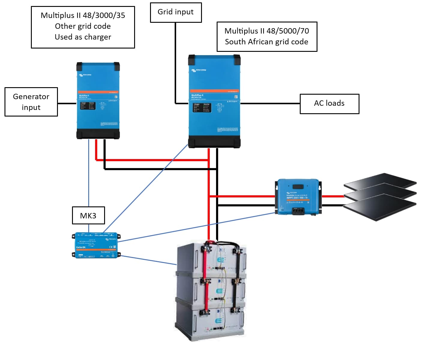
After some research I am thinking of adding an additional Multiplus 2 to only charge the bank instead of integrating a generator into my existing system as I don’t want to interfere with ESS.
Would the additional Multi be visible in Venus and managed by the BMS or would it be better to set it up as stand alone?
I don’t see an issue with this. You may struggle to track the power in from the Gen unless you add a ET112 but that’s solvable.
Why not just add another multi in parallel. Gen on on the one AC input , Grid on the other.
https://communityarchive.victronenergy.com/questions/299622/add-a-second-multiplus-ii-as-a-charger-for-a-gener.html
There is a new option in Venus 3.60 beta to allow controlling at least the charge voltage of the second Multi from the BMS. No charge current distribution at the moment (that always becomes extremely messy).
Thanks @mmaritz, this is exactly what I was thinking.
Thanks @plonkster, do you see any gotchas with the implementation Mark showed above?
I am running Venus 3.5 but will upgrade to Venus 3.6 beta. Is the current distribution for the second Multi in the works or do you mean it’s unlikely to be implemented? I had hoped DVCC would be supplied to and control charging on both inverters.
Is there any risk using only the voltage to charge the bank? Should the cut off voltage on the charger Multi be set lower?
I plan on switching the 48/3000 off when not in use. That shouldn’t be a problem I hope.
Just to add, I don’t want to automate the generator portion and plan on manually starting and stopping the generator. I could also only charge the bank to say 90% SOC and then stop the charger.
I don’t see a problem with the suggest layout. As long as you don’t use any fancy control stuff (like checking for AC on the input, or warm-up/cool-down), you should also be able to use the generator start/stop on the GX. Those extra features will control the main Multiplus (on the built-in VE.Bus port). SOC control should be fine though, since that comes from the BMS.
Thanks @plonkster.
The earthing of the generator has me a little confused. I intend wiring the generator into a two pole circuit breaker before wiring into the AC in on the inverter. Do I merely connect the live, neutral and earth wires from the generator cable to the AC input terminals?
Should I then earth the Inverter on the internal earth nut to the collective house earth from Eskom? Should all the earths in this system be common?
A while back I saw a thread here discussing the V-0-V earth tap on some generators which has thrown me for a loop.
The generator is an inverter type if that matters.
Yes.
Also, the usual TN bonding is recommended. Neutral needs to be earthed at the generator. The double pole breaker would then disconnect live and neutral, but the earth is of course never interrupted.
At least, that is the ideal. Since this second Multi is not doing anything fancy (such as ESS), you would not configure it with a grid code, and it would not do a relay check. You could then wire it in an IT-network (live and neutral are not referenced to earth and left floating), but then you also cannot have any sockets on the generator.
You would still earth everything to the same common earth, even if you don’t bond neutral.
My suggestion for testing if a generator is V-0-V, is to use an old incandescent lamp and connect it between the neutral and earth connection on the generator. If the lamp glows dimly (about 25% brightness), it’s a V-0-V generator. If the lamp remains unlit, it is not.
I have tested the voltage on the generator and the voltage between earth and live is 117 volts and between earth and neutral is 117 volts and obviously 234 volts between live and neutral so definately a V-0-V output.
If I understand you correctly, this is the preferrred outcome and is safe to use on AC in?
Not necessarily. If it is left floating, and if the multimeter you used to measure has a very high input impedance (they usually do), it is normal to measure roughly half on either side. That’s why I suggest using a small load (like a lamp). If it is V-0-V, then the lamp will actually power up. There is a proper 120V-ish present that can actually do some work. If it is floating, then the lamp will not light up, it will in fact bond T to N using a resistor. The reason for doing this, is that you cannot damage the generator/inverter.
An LED lamp might light up with very little current, which is why that is no good.
All this aside, and open to correction from others, I believe you can still use it to power the Multiplus. You just cannot configure any kind of grid code (and you wouldn’t want or need to anyway), and there cannot be any sockets powered by this arrangement (either on the input or output of the Multi.
The Multi is simply earthed to the common earth for the whole house. The generator’s case is earthed as well. No other bonding is done. The Multi will test it’s bonding relay (which it only activates when running islanded), but nothing else.
@plonkster you are an absolute legend! Our substation burnt down 8 days ago and I have been limping along in the terrible Gauteng weather, struggling to keep the power on.
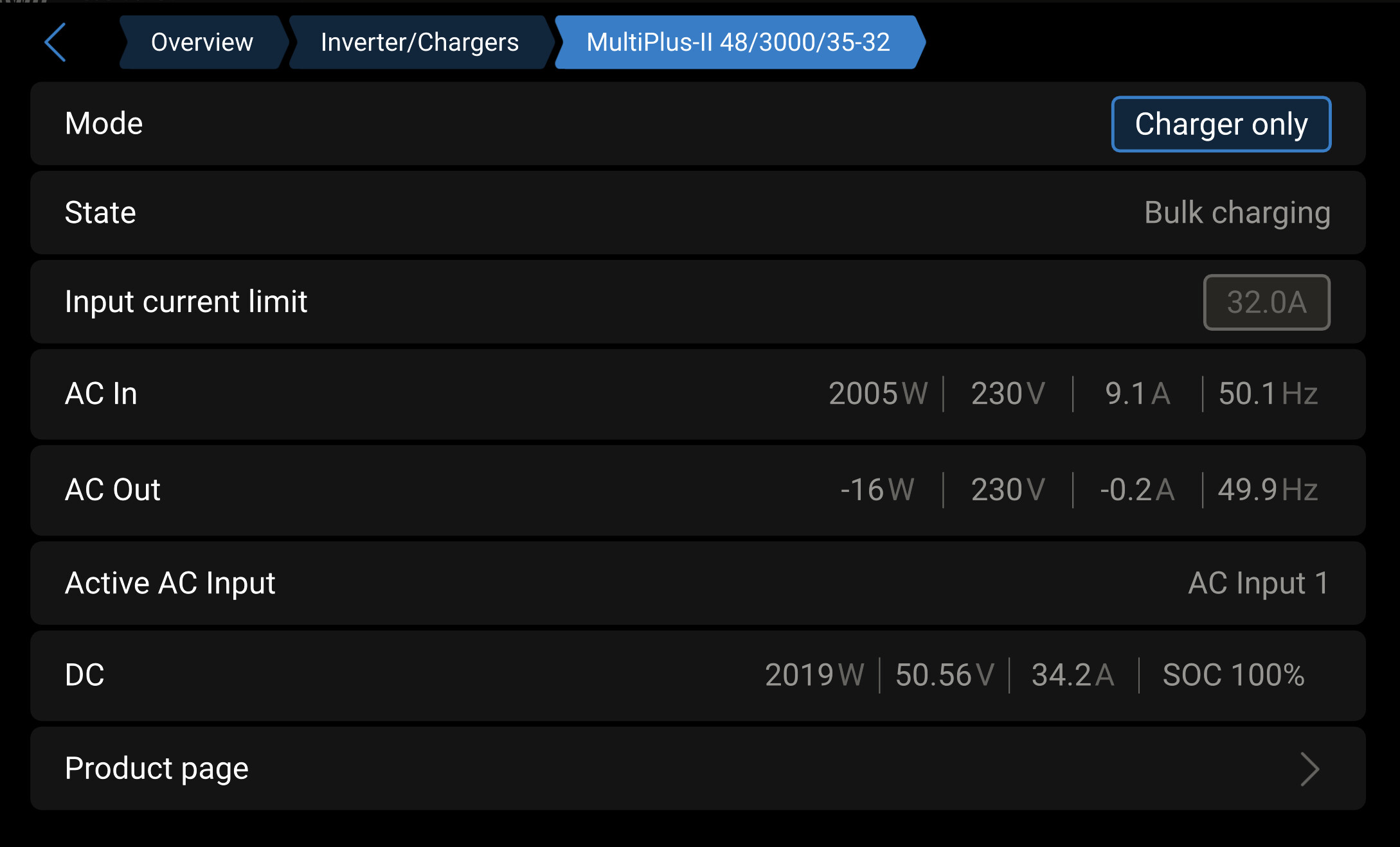
The generator works perfectly on the Multiplus 48/3000 only charging the batteries.
I upgraded Venus to the latest 3.6 beta and enabled this option: Managed battery controls all Multiplus and Quatros but the SOC on the 3000 is showing as 100% which is a little concerning.
I did configure the voltages for Pylontech according to the Victron manual in VE configure so I trust all is in order?
Aaah… yes we don’t sync the SOC from the BMS with the second multi. But it doesn’t matter, the SOC estimate is wrong, but unless you are using it for something it doesn’t matter. It will follow the voltage and that is all you need.
1 Like
Thanks for the assist @plonkster, much appreciated!