SunSynk / Pylontech RS485

Okay, I’ll try and be detailed as possible, since it might help me and someone else getting this working.
Most of the posts I’ve seen are pretty scant on details / information or are very vague.

So, I’ve tried a couple of RS485 - USB connectors.
https://www.robotics.org.za/RS485-MINI
and
https://www.robotics.org.za/W17286

At the moment, all I’d like to really do is be a able to get data out of my SunSynk Inverter, and then get some data out of the Pylontech battery. Ideally I’m trying to create my own dashboards / graphs without using the solarman app.

Creating a simple cable from a repurposed Ethernet cable, I connected pin 7 to A (D+) and pin 8 to B (D-)
(this is using this straight colour coding / labelling scheme : How To Make An Ethernet Cable - Simple Instructions) (and according to the SunSynk installation manual which I know has an error on the table for pins 7 and 8, but the diagram is correct)

Then using some basic python and minimal Modbus, (attached here)
https://minimalmodbus.readthedocs.io/en/stable/installation.html

#!/usr/bin/python3
import minimalmodbus
instrument = minimalmodbus.Instrument(’/dev/ttyUSB0’, 1)
instrument.serial.baudrate = 9600 # Baud
instrument.serial.bytesize = 8
instrument.serial.parity = ‘N’
instrument.serial.stopbits = 1
instrument.serial.timeout = 0.2 # seconds
print(instrument)
print(instrument.read_register(0))

The above as far as I understand (according to the SunSynk modbus document) should return the device type.

Instead, all I get is
minimalmodbus.Instrument<id=0x10dd9bb50, address=1, mode=rtu, close_port_after_each_call=False, precalculate_read_size=True, clear_buffers_before_each_transaction=True, handle_local_echo=False, debug=False, serial=Serial<id=0x10dd9bbb0, open=True>(port=’/dev/ttyUSB0’, baudrate=9600, bytesize=8, parity=‘N’, stopbits=1, timeout=0.2, xonxoff=False, rtscts=False, dsrdtr=False)>

minimalmodbus.NoResponseError: No communication with the instrument (no answer)

So, anyone got any ideas where I’m going wrong or can someone confirm if this works?
Perhaps my cable is damaged? Or am I just going about this the wrong way.

Again, I’ve tried to swap wires, tried two different USB-485 adapters.
Same result.

Please, I’m not looking for anything complex at the moment, just want to see if the hardware is working (and this in theory should work or not?)
If this does / should work, then I’ll get more complicated with Home Assistant.
1 Like

Hi @ozziej , I am using the CAN bus cable and using it with a Sunsynk/Pylontech comno, works great , no problems , got it with the Pylontech battery cable pack

1 Like

Okay, sorry, some clarity.

I’m already using the CAN cable to get the battery and Inverter talking to each other, this works without any issues.

What I’m trying to achieve here is to get the data out of my inverter to push it into an application like Home Assistant.

I’ve already got the Solarman app working fine with the Wifi Dongle, but I’m not terribly impressed with it as it doesn’t provide realtime data and if you want anything besides the basic graph, you have to dig into about 15 layers to get the other data, I couldn’t see any way to add another graph to the main page. This is what I’m trying to achieve.

Is it possible that the RS485 won’t work with the wifi dongle attached to the RS232 port?

Thanks, yeah got this working. sorry for the confusion, I’ve clarified my question below.

Hi.

I’m using nodered on a pi to pull data from my sunsynk and push it to homeasssitant.

I’m using a pi hat and also one of these from micro robotics. https://www.robotics.org.za/RS485-3P

I’ve tried the R30 one that you got and find it very very unstable. I’ve got 2 inverters and hence the need for 2 485 interfaces but I’ve just got it onto a single Pi 3b. From there it pushes it out via mqtt to my home assistant.

I also have the older type dongles on both inverters.

Okay, cool, so its possible.
However, how does NodeRed read the data from the inverter? (magic? what libraries / flows do I need to install?) Do I just install node red and it works?
I mean, can you share more info?
Can you upload pictures / wiring of the cable? (Perhaps I’ve got something wrong - anything is possible at the moment)
Sorry if this comes across as sarcastic, but I’m getting absolutely nowhere with this and cannot diagnose any steps because I have no idea what is or is not working.
I’m quite happy to actually write a how-to on this (if I can get anything working) and I’m really not an idiot, but this is frustrating the hell out of me.
I need somewhere basic to start.

  1. Is my cable right ?
  2. Does the USB-RS485 adapter work?
  3. Is the inverter getting the request ? If so how do I verify?
  4. Can I have 485 and 232 connected ?

This is the problem with serial comms!
One suggestion is to use a breakout box to monitor data on the link. See: https://en.wikipedia.org/wiki/Breakout_box


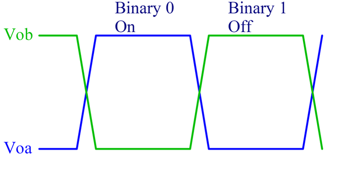
This is a graphical representation of RS485 signal levels.
It is referred to as a ‘differential’ signal since the data depends of the voltage difference between the two wires. (i.e. no reference to ground is required)
So there will always be the same voltage difference between the two wires but the polarity swaps when transmitting/receiving data.
RS485 signals are polarity sensitive so the +ve connectors (and negative) must be connected together…
RS232 is different from RS485 since it references 0V and isn’t a differetial signal. These two standards are not compatible unless a converter is used to convert the signals.

That second USB to RS485 converter has LED indication of data being received or transmitted so that should be helpful.

Okay, cool, this is exactly the understanding that I have already from most sites explaining the difference between the two.
Yes, the second one does show data Tx, but that’s it.

I’m curious how so many people have “just got this working” but no one seems to be able to provide repeatable step by step instructions.

I’m mean, surely there is someone on this forum that has got this working, that made some kind of notes as to what works or not, or at the very least can share some information.
What I’m looking for is :

  1. What kind of USB - RS485 converter are you using?
  2. What cable are you using ? Can you share images / diagrams (if nothing more than for validation) ?
  3. What platform ? Windows / Linux / Docker ?
  4. If a pre-compiled / pre-packaged tool, what is it ? And what additional packages were required? Modbus? RS485? SunSynk specific ones?
  5. If not pre-packaged stuff, again, what version of Operating System? What language Python, C++, etc? What additional packages were required for this? Minimal Modbus?

I really struggle to understand why this should be so difficult… I also do not understand why these companies do not want people to integrate their systems.
Why is this so secretive ? There is some documentation but its so fragmented and inconsistent.

1 Like

My sympathies to you and myself for trying to get to grips with these things! Older PLCs etc. used these protocols to connect with them and you needed a bunch of specialised cables with the appropriate converters to program them. (Then Ethernet emerged and blew them all away!)
My suggestion is to collar both suppliers of their devices. Speak to the guru (not the salesman!) and check what they say…
Also find out who has managed to get this link working. (ask around on all the forums…) If you have to take your setup (minus the inverter) there and check if it works on that system…

@Vassen
@Ryeman

Would any of you be willing to share some more info?
This seems like a few people would love to know how to get this working, but it just seems like there is no simple / concrete info around.

Documentation is like sex. When it is good, it is good. When it is bad, at least it is better than nothing.

:smiley:

I hope you’ve got your documentation ducks in a row… :duck: :duck: :duck:

Well, I’m pretty sure the guys in prison would rather have the nothing :sweat_smile:

Check the last post on this thread: Sunsynk guru/help needed
Help might be available from the Sunsync forum…

I am successfully using the second device also purchased from Robotics:
https://www.robotics.org.za/W17286

Not linux or Pi expert (using RPi4) but also did it by trial and error to get modbus working. I used these steps.

Modbus tutorial: Modbus Tutorial from Control Solutions

Modbus port setup:
sudo systemctl stop mbusd@ttyUSB0.service
sudo systemctl start mbusd@ttyUSB0.service
journalctl -u mbusd@ttyUSB0.service -f -n 10
udevadm info -a -p $(udevadm info -q path -n /dev/ttyUSB1)
sudo vi /etc/mbusd/mbusd-ttyUSB0.con
cat /dev/ttyUSB1

Install modbus tcp:

sudo apt-get update && sudo apt-get upgrade
sudo apt-get install cmake
sudo apt-get install git cmake -y
git clone GitHub - 3cky/mbusd: Open-source Modbus TCP to Modbus RTU (RS-232/485) gateway. mbusd.git
cd mbusd.git
mkdir -p build && cd build
cmake -DCMAKE_INSTALL_PREFIX=/usr …
make
sudo make install
sudo systemctl enable mbusd@ttyUSB0.service

Then I used Nodered to read the serial port.

Hope this helps

@Ryeman Thanks! This looks promising…
I’ll give it a try today and provide feedback.

Sigh. Still no progress on this…
So, using the suggestion of this :

I installed and configured it to this:
file : /etc/mbusd/mbusd-ttyUSB0.conf


device = /dev/ttyUSB0
speed = 9600
mode = 8n1
trx_control = addc
address = 0.0.0.0
port = 502
maxconn = 32
timeout = 60
retries = 3
pause = 100
wait = 500
replyonbroadcast = no

(Very important here is the file name and how you start it, filename and service name must be exactly as here)

Then enabled it :

sudo systemctl enable mbusd@ttyUSB0.service
sudo systemctl start mbusd@ttyUSB0.service

or you can run it in non-daemon mode like this:
sudo /usr/bin/mbusd -d -v2 -L - -c /etc/mbusd/mbusd-ttyUSB0.conf

I then did :
sudo pip install pyModbusTCP

and
git clone https://github.com/sourceperl/pyModbusTCP.git

The git repo has some examples to try it out.
inside the directory it will create:
pyModbusTCP/examples
one of those is :
read_register.py
You need to enable debug in the file:
(here is the contents without comments)


from pyModbusTCP.client import ModbusClient
import time
SERVER_HOST = "localhost"
SERVER_PORT = 502
c = ModbusClient()
c.debug(True)
c.host(SERVER_HOST)
c.port(SERVER_PORT)
while True:
    if not c.is_open():
        if not c.open():
            print("unable to connect to "+SERVER_HOST+":"+str(SERVER_PORT))
    if c.is_open():
        regs = c.read_holding_registers(0, 10)
        if regs:
    time.sleep(2)

When the above is running and you make a connection, you’ll get output like this: from mbusd.

Aug 19 12:37:07 raspberrypi mbusd[1192]: 19 Aug 2021 12:37:07 conn_open(): accepting connection from 127.0.0.1
Aug 19 12:37:17 raspberrypi mbusd[1192]: 19 Aug 2021 12:37:17 conn_close(): closing connection from 127.0.0.1

The output of the read_register.py executable is :
Tx
[B5 84 00 00 00 06 01] 03 00 00 00 0A
Rx
[B5 84 00 00 00 03 01] 83 0B
except (code 11)
Tx
[DC D1 00 00 00 06 01] 03 00 00 00 0A
Rx
[DC D1 00 00 00 03 01] 83 0B
except (code 11)

And this is where I’m stuck, it seems like this is not working.
(it keeps reading register 0 and reports an error (83 0B)

Not sure where to go from here…

1 Like

@ozziej start by providing as much info as possible.

What hardware are you using to try and achieve this?
What OS/distro are you running on this?
Is the RS485 adapter the only USB device plugged in?

I see you refer to “/dev/ttyUSB0” but have you confirmed this device exists or is infact the correct device?

Hi, Answering your questions in your order.

  1. Raspberry Pi 3B+ and RPI 4 4GB as well as MacBook Pro
  2. RPI OS 32 Bit as well as Mac OS 11.5.2
  3. Yes, only USB device plugged in.
  4. Yes, 100% sure its the device and its the correct one. (I can see the status Tx light blink when sending commands)