Cool beans. I feel this is something I “must” have.
These testers are great to have because they allow you to test a cable easily. One cannot access the contacts of these RJxx plugs with a multimeter.
I managed to blow the sequencer IC in my tester so I replaced it with a tiny rotary switch (and got to understand the circuit which is a clever design)
Speaking of design, I thought I’d share something that I learned yesterday (which all of you probably knew hahaha ![]()
So seeing as my new connectors arrived yesterday, I though I’d give it one more go to try and successfully crimp 2 old connectors on a long piece of Cat 6 cable I have. (refer to a few posts above where I couldn’t get it right)
I figured, copper remains copper and a device cannot distinguish between the colours of the inner strands right? So as long as I ensured that the colours correspond exactly in both connectors, and that all of the 8 strands are used/available to the device at least, whatever the purpose of a particular strand.
So I positioned the strands in an order that is easiest to work with for insertion into the connectors (not bending and twisting them in weird ways to get them as the colour sequence diagram wants it to be)
Triple checked both before crimping but alas, no internet signal to be had through that cable. Dumbstruck I was.
So merely to amuse myself I googled a bit on what the issue can be.
Turns out that specific colours need to form a pair at both ends (despite these not necessarily traveling as a pair through the length of the cable), for the signal to be correctly interpreted/modified or whatever, and this is achieved in the way that the pairs are coiled. ![]()
So for example, short tighter coils will create a different signal than a pair which is coiled in longer strokes. My layman’s understanding of what I read.
So I suppose it has to do with magnetic fields or something that is created?
Maybe someone can give a better explanation, but it was both fascinating to learn this and also left me with a sense of why? This seems an unnecessary weird/difficult design concept.
I remember this from first year university physics. It is called the right hand rule. When current flows in the direction of the thumb, there is a magnetic field going around the wire in the direction of your other 4 fingers.
Another conductor in the same vicinity as that one will pick up on that magnetic field, and it will turn back into a current in that conductor.
But if you put the two conductors that carry the same signal (but in opposing directions) close to each other, and on purpose entangle them a bit, they cancel out.
Don’t do that, and you get all kinds of weird cross-talk.
Edit: If you are up for another experiment… as long as you keep the pairs in the right places, you can swap them around. You will have noticed the wires are pairs, as in blue+blue/white, green+green/white, orange/orange+white, etc etc. You can swap the colours, as long as you keep the pairs. This is fine for CAT5. For CAT6, where there is an additional separator inside the cable, using the right pairs makes a difference again.
Edit 2: A note on what “Cross talk” is. Remember back in the 80s/90s, when you called people on an old analog exchange, and you could hear indistinct voices of other people in the background very softly? That’s cross-talk. Signals from other wires interfering with the signal on your pair. At an exchange, there is a LOT of cross-talk, because a lot of wires come together. This is the main reason that for ADSL (which is now also going the way of the dinosaur), the speed was async. Download was faster than upload. They used a large amount of sound spectrum in the download direction than the upload direction to reduce cross-talk on the exchange side. I forgot the precise details of how this works.
I smiled at this … if I had been inclined to do that, and I will take a bet with myself too, that I would have blown something up.
Thank you for doing it though, I always wondered why the wires were like that. Now I know.
Damn clever if you ask me.
This is called a ‘differential pair’ or ‘twisted pair’ in the lingo.
It’s so good at noise immunity that the regular LAN cable isn’t screened. Screened cables were essential in industrial environments for analog or digital signals (and probably still are as a precautionary measure)
I always say that computers are very spesific (electronics is the same) in that it is looking for spesific “contract” between parts to work. If you change the wire connections, change the data field name or data type you are changing the contract and so the hardware or software needs to change to be adjusted to handle the new contract.
This is what your see in the network cables as well. The 4 wire pairs are pairs inside the wire (mostly for minimising interference as Richard mentioned) but on the connector side they are not pairs anymore and each has a spesific pin that it is contracted too. Or else it will not work :). You can swop some wire positions. There are 2 standards that swop the green and orange pairs, but the blue and brown is always the same.
Sometimes there are a bit of leeway included in the spesification. For instance POE can use some of the 8 wires inside the cat for powerlines, but this then sacrifice some data lines and limit your top network speed. However you can only use spesific wires for this which the POE injectors use.
1 Like
Always use the standard if you have a choice. For the people who come after you ![]()
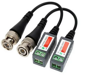
Also see these things, typically used in CCTV applications, which can push video signalling over twisted pair. Normally, you’d use coax with a screen…
That is sometimes referred to as “common mode” noise, or at least, that’s what I see in the literature. It means that when there is interference, it affects BOTH signals in the same direction, while the signal itself is flowing in opposite directions (differential).
Fascinating thank you guys!
I went to have look quickly. I joined a Cat 5 (grey) & 6 (orange) cable.
I forget which one (but think it was the orange), but one of them has a plastic divider type thing inside which keeps some of the pairs apart. The grey cable however also has 2 other things inside:
- a metal foil shielding; and
- an exposed solid wire
But the joint work.
I laughed out loud about your comment though! It is a pleasure, I also like to learn!
Yes! Will do that in future.
That provides additional separation and insulation, to reduce cross-talk. The divider is also twisted, which means the pairs themselves twist around each other.
I don’t think I’ve ever seen that. Not all CAT5 has the shielding either, but I’ve seen both kinds. Some also have a thin strip of rope in it, a ripcord. That’s there to allow you to rip through the insulation without using a knife.
Yes, but what’s the packet loss look like at full speed?
I love standards, there are so many to choose from.