Sorry, unfortunately I don’t know.
Take one of the good ones out and measure the clamping voltage. The 6V feels too low for CAN, usually you get can protection devices that are 2 tranzorbs in one package and around 20V. But as stated, removing a tranzorb should restore functionality to test.
Ok, thanks.
No worries, thanks
Hello,
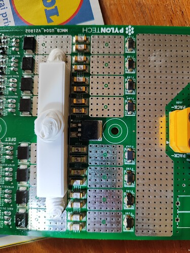
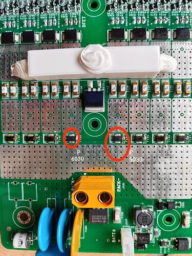
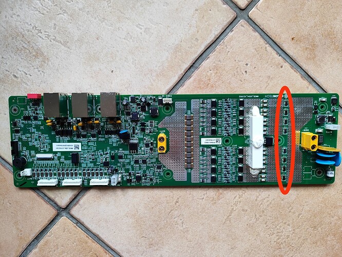
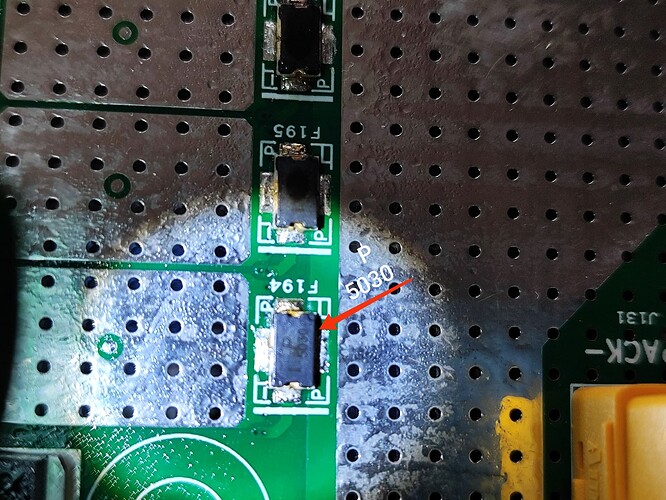
One of my 4 Pylontech us3000c BMS board has burnt. It seems that the 8 components identified from F190 to F197 has burnt. I can read the reference P 5030 or P 6030 but as they have burnt it is not sure.
Have you an idea of what are these components ? It is a rearmable fuse ?
Thank you in advance for your help
Jean
Welcome Jean.
Get a new BMS?
Thank you for your answer
Why should I spend 400€ if the my current BMS board can be fixed by replacing 8 components ? It might not fix the problem but I would like to try.
Jean
Someone will be around to reply on your question.
PS. 400€ is quite expensive?
Link I saw here:
It’s ZAR8000, half the cost price of the whole thing.
F is normally for a fuse, but if I had to guess it is probably a FET. It could be an FDP6030. Don’t know the thing at all, just a wile guess.
Edit: I think I am wrong with that guess. It probably is a fuse. In this video, around 3:35, he calls it “Thermo-fusible”… it might be a thermal fuse. Google translate says the video is in Romanian.
Agreed!
I downloaded the pic and drilled down to try to see what was burnt. I failed…
More information is needed: Where is @Henaffj ? I ask because as an electronics tech one needs to have a look to see what we are dealing with…
Is it one only or are there other batteries with the same PCB. (There are no schematics these days so the electronics tech has to dig deep…)
Yeah, they are fuses. Another video where someone seems to have the same issue, though they show no signs of damage nor smell like it. Seems like this is exactly what you need.
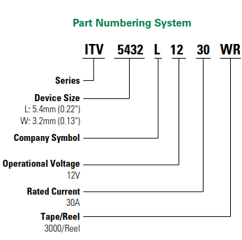
The part number is ITV5432L5030.
Note that there is a reason those fuses failed. It can fail for two reasons, either there was an actual short and they failed due to overcurrent, or the BMS’s secondary protection kicked in (in the above video that happened because another FET failed) and it blew them using the internal heaters. So you may want to do what he did… first replace with a cheap fuse, something smaller will do, just to make sure it works.
Hello
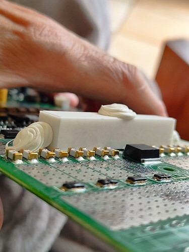
Thank you, here are 4 additional pictures. I can read P5030 in one component and P6030 on another one. For the others I can’t read because the components are damage.
I’ve 3 other devices so you are right I’ll open one of them to try to identify the components.
FET means FET transistor, right ?
Best regards
Jean
FET means Field Effect Transistor. The most common type is a MOSFET, a metal oxide silicon FET. But that doesn’t matter. Those components are fuses. Very clever special fuses that can be blown up electrically. The battery has multiple protection mechanisms, and one of them is to blow the fuses electronically. I assume this is a last measure. See the video I posted above.
You can replace the fuses, but they may just blow again. So you have to check if they are being blown electrically (ie there is a voltage on the trigger pin) or not, and work from there.
While I doubt it is really 6030, it would not matter. That’s the nominal voltage of the component, and the 5030 is rated to 62V which is ample.
Thank you for your quick answer
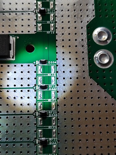
Here is the back of the board
There are diodes, I guess that they are used to trigger the fuses
Regards
Jean
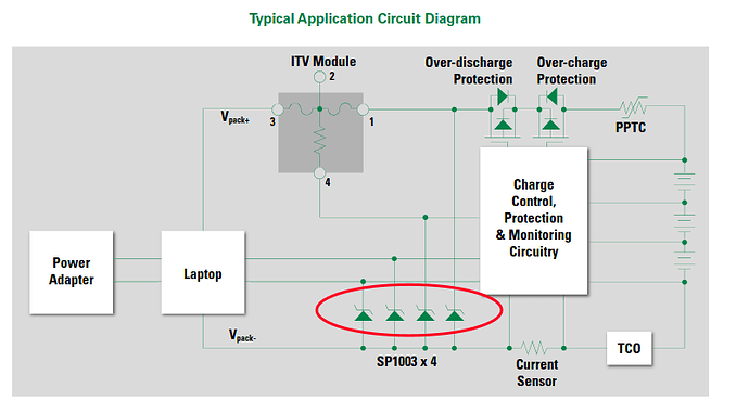
So, the way I read that circuit diagram, normally pin 4 is at the same potential as pin 1 and no current flows through that internal resistor. If you measure from pin 1 to pin 4 you should get no reading, or a very low one. Then, if something goes wrong and it needs to activate protection, it will pull pin 4 down to ground. That causes a large current to flow from pin 1 to pin 4 (or from pin 3 to pin 4 during charging) and blow the fuse.
On the Pylontech board, there is a MOSFET (shown in the video) that pulls pin 4 down. If that FET fails short-circuited, then putting in new fuses just causes them to blow again immediately. So you must also check that FET.
The “diodes” on the board effectively does nothing. They are just there to suppress transients (they will be reverse biased most likely, can’t see from here).
If the component is 5030 then it means 50V and 30A, isn’t it ? Why did you write 60 V ?
You wrote 62V, is it a mistake?
Dear Plonkster,
Oh ! I did miss the video, I’ve just watched it and this is exactly my issue. Thank you so much for your help and the component reference.
Regards,
Jean
No. The nominal working voltage is 50V. Look at the specification sheet I linked, it shows that the voltage range is somewhere between 45V and 62V.
