I’d like to see your maths on this.
Even large ferrite beads will add a couple hundred nH max.
For an inductor, you get V = L.di/dt
Which you can rearrange so that V/L = di/dt
So let’s say you can get 1uH of inductance, with 50V across the inductor initially
(assuming the caps are discharged and the battery is about 50V) you have a
di/dt of 50000000 A/S (Or 50A/uS), which isn’t going to limit the current enough.
Not to mention that your ferrite bead inductor will saturate at a very low current
and once it does, it’s like it doesn’t exist.
I could run a simulation with a small inductor and large capacitor and put a 50V
step change on it to show you what would happen, but I don’t have the time right now.
1 Like
I’d like to see that when you have time.
Like you, I think 1 uH, is probably too high, - let us use 200nH then.
The cabling involved has a resistance of around 2miliohms (10m of 100m2)
I don’t know what the capacitance of the inverter is, but 60 000µF was suggested above.
My own thinking would be to determine the approximate frequency of the CR circuit without the bead:
T(secs) = CR = .06F x 0.002ohms = 0.00012secs
This would represent the first rising edge of the sine wave, so 4 times longer would be the total time of a full wavelength (0.00048secs) which approximates to 2kHZ.
So Inductive impedance added to the circuit at 2kHZ is 2(pi) F .L = 2.5mOhms.
So even by my own thinking, a ferrite bead will only just double the impedance of the cabling. On the other hand, doubling the impedance will halve the current.
Yeah, I know I have substituted absolutes for the dynamic quantities that will be in a model and am probably way off, but like I say I am interested in what a model spits out with the same parameters.
Thanks, I see some of the others are also “R 2.155 each (On a Reel of 3000)” ![]()
Makes sense that this configuration has a specific name, even “LED driver”. Suppose that should have occurred to me yesterday.
Will see if some other things can soften the R95 delivery cost. In other news, I might want to unload 15-19 constant current diodes soon…
I will do the simulation shortly. I should have a few minutes now.
Unfortunately you are over-simplifying it a bit. The RC time constant you mention is the time for the voltage across the capacitor the climb to 2/3 of the applied voltage. So for a 50V battery, that’s the time for the capacitors to reach about 33V. The current into a capacitor is C.dv/dt , i.e. It is governed by the rate of change of the voltage across the capacitor (or conversely the rate of change of the voltage across the capacitor is determined by the current through it. Where as the effect of the inductor is determined by the rate of change of the current, so it’s a bit more complicated when you put them in series. You will also be making a resonant circuit, so the voltage on the capacitors will almost certainly oscillate a bit before settling at the battery voltage.
Anyway, the simulation will be quite easy to do. I’ll post the results here in a bit.
1 Like
Ok, so it seems I was wrong about the oscillation.
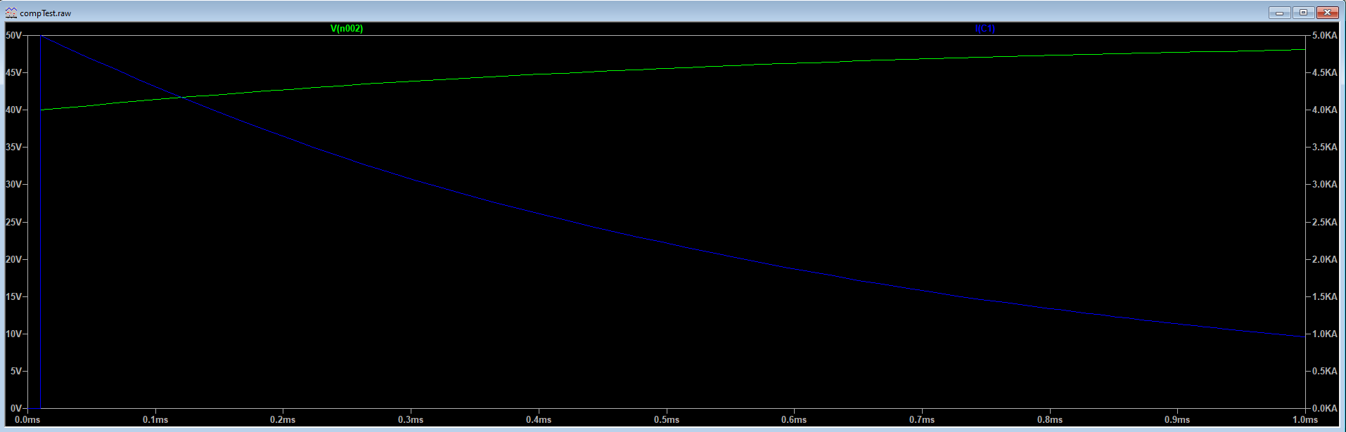
I simulated it with 100nH inductance, 60000uF capacitor and 10mOhm series resistance.
(The capacitors themselves and the battery also have some resistance)
I applied a 50V step change and got this: The green trace is the voltage across the capacitor and the blue trace is the current, which peaks a bit over 4.5kA

Then I re-ran the simulation with the inductance changed to 1uH (much more than you could get in practice with a ferrite bead). You can see it does make a difference, but not enough to get excited about. The current peaks at just under 4kA.

I just had what may be a terrible idea (not sure yet) put all your constant current diodes in parallel as your pre-charge (instead of a resistor). 20 of them should give you 600mA. If you put an LED on 1 of them then you can still have your indication. i.e. 19 of them are just in parallel and the 20th one has an extra LED.
@Stanley, Thanks very much for that.
I am interested in what the peak would be without any inductance?
That would show what the beads effect is.
The reason I added 100nH in the first simulation is because you always have some inductance. Even a straight piece of wire has inductance. The capacitors have a small ESL (equivalent series inductance). The battery cables form a loop, which increases the inductance.
I ran it quickly with no inductance for you anyway as an academic exercise, and it looks exactly like I would expect. The current starts a 5kA (limited only by the 10mOhm resistance) and then tapers as the capacitors are charged.
@Stanley Ok it seems like a ferrite bead is fairly ineffective at suppressing this charging current surge.
What are your thoughts as to what they would bring to the party during a lightning strike?
I don’t think a ferrite bead would do much to help during a lightning strike, but I could be wrong.
1 Like
I think it differs from the charging model in that there will be many potential parallel circuits to earth to discharge. The circuits that allow an instantaneous impulse will bear the brunt of that discharge.
If your model was a discharging capacitor with two parallel paths 1 with 10mOhm resistance and 1 with 10mOhm resistance and 100nH bead. I think that a lot of charge would have dissipated before the bead circuit current peaked.
So I think it could offer some, albeit limited, protection.
In any event, it seems that although it doesn’t make things good enough, it still makes things better.
For a lightning strike there are a multitude of ways people have come up with over the years. Don’t know what the latest techniques are. Many years ago when I had to protect a couple of serial communication lines we used some gas discharge devices an inductor/fuse and a zener. The gas discharge device (spark gap in a glass envelope with some gas) was a bit slow so the zener took the initial bit of current before the gas discharge device arced up. The inductor just helped the voltage rise at the other protection devices. Problem with these things is you don’t know how well they are working unless you have two circuits one protected and the other not. Otherwise if your circuit survives a a thunderstorm you don’t know if it was because the protection or because the lightning did not get close enough.
I think it is pretty difficult to survive a direct lightning strike.
This is all a bit different to charging large capacitors.
I agree, even the best surge protection will most likely blow up. When I used to work in an engineering office the only way to cover equipment and personal was with rods and masts to direct lightning straight to ground and then let the surge protection cover the surges.
Yes masts and wires strung between masts will attract the actual strike. The induced energy is still substantial for any cable near the strike and any cable running down the mast will have enough induced onto them to cause melting of components.
I am happy that I have never been close to a strike. My wife however has been close to two strikes. No ill effects other than a higher than usual concern when a thunderstorm approaches.
What I do to pre-charge the caps on an inverter is use my adjustable power supply. I connect it and start with a low voltage, like 3v and turn it up slowly to 48v. No inrush at all…
Not common for someone to have a 48V DC PSU.
I had one that could do 30V (but it died on me)
Sounds like current limiting, but with extra steps. Seriously, just set an appropriate current limit and it will take care of itself.