New Solar planning and design guidelines

The short high level list of what you need would be something like the following:

  • PV panels connected in serie to get to your PV voltage (PV string that give you your PV voltage. Say 150V)
  • Multiple strings need to be connected together (combined) in a combiner box with each string having a DC fuse. You also need surge protection here. (each string combined will give you your PV current. Say 30A for 3 stings)
  • You need DC cables to take your combined PV to your MPPT
  • Just before your MPPT you need a DC rated breaker where you can disconnect the PV
  • Then you need the MPPT that use the 150V/30A. It will give you your DC bus with (almost) constant voltage. This MPPT can be built into your inverter or seperate.
  • The inverter naturally
  • Battery cables between inverter and battery. Some sort of disconnect for the battery and also fuse/breaker.
  • battery

Fuses and breakers are installed to protect your wires. If you wire can handle up to 18A current, then your fuse need to blow before that, so it must be smaller (16A for instance).

NB! You need to calculate the current and voltage for each device and wire and use the correct ratings at each step. If you don’t it can be unsafe, or even dangerous. If you don’t have the expertise it is better to get a professional to do it for you.

NB2! You may never exceed the voltage rating of a device, so always keep a safety margin below the max voltage. In most cases you can exceed the current rating of some devices (it will just not be used), but not the current rating of any cable.

Basic example of how the voltages in a PV system work. I will use a Victron system as it is easy to follow.
I have a 400W PV panel. It’s normal rating is 40V giving 10A. It’s Vmax is 47V.
For a SmartSolar 150/70 I can do 3S2P (2 Parallel strings each with 3 PV panels in Serie). This will give me 3x40V=120V and 10A (below the 150V max of the MPPT) which is 1200W (120V x 10A) per string. 2 strings means double the power 2400W (120V x (10A+10A)).
My 6mm PV DC cable is rated 600V 30A so will hande 120V and 20A.
The MPPT will take the 2400W at 120V and convert it to my battery DC voltage at 48V which will be 50A (2400W/48V) below my MPPT’s 70A rating.
The battery can give (discharge) 100A, while it can recieve (charge) 60A which is below the 50A.
If we use the Multiplus II 3kVA it has a continuous rating of 2400W which is the same 50A from the MPPT and the battery can handle that. But being a Victron it can peak at much higher 5500W or 114A at 48V and so our battery will trip at that current. Thus you need to limit the inverter max power and we also need our battery cables to handle 120A and a fuse for that.

Tip: When comparing inverters use the spesifications to get the avg. and max values and do the same calculation as above. Never use the lables or model numbers or marketing mumbo jumbo. The power that a 3kVA model from brand one can give you might be more than the power brand two’s 5kW can give you. One brand will market is as what the inverter can give you constantly while the other market it as the peak it can give you for a second.

Tip: If you plan to DIY then don’t buy the cheapest stuff. Buy those with the best support and the most dummy proof. Let’s face it if you are not a professional in that area, then you are the dummy and you will make mistakes.

2 Likes

Also remember that this is temperature dependent. The number quoted on the spec sheet is at 25°C.

The Voc (voltage open circuit, same thing) of a module can be over 50V if it gets cold enough. For example the Canadian Solars on my roof reach 50V around -7°C.

As a rule of thumb, take the number of cells in the module (just count the squares, it will usually be 72), and multiply with 0.7. That is what it makes when it is really cold. Multiply it by 0.6, that is what it makes open circuit on a normal hot African day. Multiply by 0.5, that is where it runs when making maximum power.

It’s not a question of when it’s needed. It’s always needed. Just in different forms.

For a low voltage inverter like the victron of some of the axperts, you are combining multiple strings in parallel and I think that’s where the name came from.

For a 8 kw sunsynk, you can also have 2 strings per mppt so a 2 in, 1 out combiner box can be used.

For the 5kw sunsynk, your combiner box is then simply a 1 in, 1 out.

For all of them, you still need the dc breakers, fuses and surge protectors.

So the fuses are per string and the dc breakers and surge is per mppt.

For the battery cables most people use a combined breaker / fuse but this can also be separate.

For battery cables, it should ideally be specked for the absolute max current draw/ charge rate from inverter and not on the size of your battery bank.

Battery cable should also factor in length, longer cables means thicker cables

  1. Model the same household for off grid if the first model does not quite make off grid and see what it takes

Can we go off grid now please….

Lets compare, original barebones on the left, off-grid model to the right, and no, you cannot go off-grid with the barebones system. Well not if you continue to consume the same amount of electrical energy.

1364807211_Screenshot2021-10-11at07_03_24.thumb.png.70006e6c3577e94e0e59efb3eb652932.png

Upgrades done from barebones. Increased the number of Panels, changed the Inverter for a 8kW unit and added battery capacity to last for a winters night.

Things to keep in mind. Panels do not face true North, panel tilt angle 20deg. I just added battery packs as if you were expanding the barebones system, but had to change the inverter to cope with the panel string voltage. If the original inverter could cope, you could leave that alone as well, so purchase a HV PV model in the first place. When designing, keep future requirements and expansion in mind. Always design for the end game, or what you believe the end game can be, that way you can prevent extra work and upgrades in future, sometimes.

For both these systems, the RoI is better than most other ways to invest money (this is not financial advice as I am no financial advisor, please do your own validation). The smaller system has a better returning and lower cost of energy but the bigger system save you more and gets to reduce your monthly bill to basically R0.00 if you had a bill at all. The bigger system also makes you independent from energy price increases (funny how you never see a decrease ne), availability issues and gives you full control over your energy production and consumption. Just the annoyance factor elimination may be worth investing in Solar, any Solar. That and the energy independence is priceless.

Comparing the performance from a generation and consumption perspective.

1998693581_Screenshot2021-10-11at07_06_55.thumb.png.1babc36ce5447589ddcb6e44ab703e06.png

With the barebones system, we not generating enough solar to cover our loads completely. There should be enough to recharge the battery and carry some of the load during daytime (and the option to charge batteries from Utility grid is there). It should cover some load shedding or blackouts rather well but. That kinda depends on how severe the blackout levels are. For the off-grid modelled system, to be able to carry all loads and recharge the battery system at 26.4kWh, we need a bit more Solar panel, in this case 20 panels. For the Summer, Fall and Spring seasons, we should have enough panel to cover for a day or a few days of overcast or rainy weather and still carry loads and recharge batteries.

During Winter however, this may be challenging. Purposely, I did not optimise the panels for Winter generation bias as that will mean a non standard roof installation, and extra time and costs. Optimising the panels for Winter production in this case may just reap enough extra energy to cover battery charging back to 100% and carry all loads. That will have to be determined for each case tho. In an off-grid install, there is no feed in to any grid at all. So excess energy generation potential will go to waste, ie not generated as the system will be throttled, if not self consumed. This is where Hot water storage will benefit, as well as Heat pump Airconditioners due to their heating efficiency as well as its cooling efficiency. We can discuss why this is so for heat pumps later.

Savings.

319096264_Screenshot2021-10-11at08_03_44.thumb.png.1f6d9acb5085db62e394c46628fbe5aa.png

This is the influence on your monthly bill for each of the 2 systems.

What is the break even point for these systems? Comparison between the estimated net savings for each system and the break even time period.

723362299_Screenshot2021-10-11at19_37_30.thumb.png.a499953c82514c5cead1db28dea1a5cd.png

If your requirements are for a simple system to beat load shedding, you do not need much in terms of equipment. As is clear from the above, a relatively small investment (not these numbers or these specific equipment pieces) will get you to your requirements. If you have more of a lofty goal, you will need a bigger budget to get where you want to be. These two options used here are for illustrative purposes and should serve as a guide of what is involved.

More on this financial aspect later…

More better later, is now :) We continue with the models. Also, as to costs and payback and savings, all them boring Financial stuffs….

Energy flow and the typical usage for a home. In the below we can see when, on average, people use energy in comparison to when Solar energy Is generated. Above the Zero line is generation, and below it is consumption. This makes it clear why battery use is so important. The grey parts of the graph is energy consumption that cannot be satisfied by either Solar generation or battery supplied energy. This means the following, If you have only a few panels and the grey part of the graph overlaps with the yellow Solar part, you do not have enough panel. Early morning and late afternoon this is normal as the Sun is rising or setting still. During nighttime the only way to not be a net consumer (ie from the Utility grid) is to have alternate generating capacity other than Solar, or battery storage of sufficient size.

Compare the barebones system to the off-grid one above to see the effect of enough Solar panels and battery capacity. These two parameters were the only changes between the two systems affecting energy flow.

86809611_Screenshot2021-10-13at11_32_00.thumb.png.28b4874205254f12bdbe84e205b39c67.png

For Winter below, in comparison to the other seasons above, we can see that the energy usage pattern differs a lot. During Winter use, we have almost no excess energy (export) for the Barebones system and 44% less energy excess during the daytime.

110752798_Screenshot2021-10-13at11_33_40.thumb.png.2ccfaa4b0d56ed4f67f70e8d2495f9cf.png

Here we are looking at the financial comparison. The difference is clear. Remember that Values below is actually your future savings projected to today in today’s value of your money. The blue on the flows are battery capacity being used to carry the loads above the Zero line, below the line is battery charging.

1252252695_Screenshot2021-10-13at11_38_05.thumb.png.1b95d448008faa416d95e946473fc1f1.png

Again I need to stress, this is not a systems design. You cannot use this system, any one of these two designs, to build your solution as this is far too simplistic and was only put together to ba able to this comparative modelling. It is merely done to give you the insight what to look for and how to got about YOUR planning. We will show you how to do this planning in a future post, but you need to do that planning, or pay someone to do that for you, or ask on the forum here for advice etc. You need to find the equipment brand at a suitable price to make this work for you.

Also important is how you look at off-grid. You have to make a choice on a few things. Do you want to spend anything on a monthly bill? Do you want to keep the Utility grid and still consume energy from there? Are you looking for just blackout protection to ride out the Utility grid failure? All these items have a material influence on how you approach your design. For some people it’s simplistic and their requirements will be different from yours or my requirements, only you know what your requirements are. There are a number of pre-packaged solutions and DIY systems out there, all of them are based on some requirements.

The only thing you have to base your decision on are your requirements, so better get to know that intimately. If that is not the first thing asked, about your requirements, assumptions were made and those assumptions in your case may very well be incorrect, resulting in a system that may not be suitable to varying degrees.

Next time, Alternate fuels and ways to reduce the electrical loads.

Alternate energy or fuels, what ya mean alternate, energy is energy, no….

Well yes and no. Let’s unpack this a little in terms of Solar generation. There are two ways we can harvest enough Solar energy via Solar PV panels. One is to generate enough to cover our consumption 100%, the other is to reduce or electrical energy consumption by changing over to other forms of energy, normally chemical (fuel) energy or other forms of Solar like direct water heating. This will reduce or electrical energy consumption, sometimes by a lot.

In SA, our fuel prices are well regulated. All fuel types BTU values per unit is known and the relative pricing is done accordingly. Here is a table for clarity sake:

4631755_Screenshot2021-10-14at12_12_37.thumb.png.49411f12a9a08166407c63614c4e8f25.png

Let’s compare electricity to LPG gas and to Diesel fuel. First LPG and Electricity. LPG gives 24 098 Btu per Liter (or 45 545 Btu/kg) and it’s density is 1.898 kg/m3 (15°C) (roughly 1.89kg/L). Let’s work on the average price of R30.00 per kg for LPG and electricity at R2.00 per kWh. For the same Btu value, electricity will need 13.34x more units to get the same value and will cost R 26.68 vs R 30.00/L for LPG. See what NERSA is doing here? Anything that directly competes with the Utility grid ne, priced out of the market… Obviously the LPG price differs per region and there are similar differences for Diesel, but suffice for this demonstration to use averages to illustrate the tight control over our energy prices.

Diesel is very close to half the density of LPG. Diesel gives 36 675Btu per litre (or 32 090Btu/kg) thusly you need 10.75x electricity units to match Diesel’s energy or R 21.50 worth of electricity vs Diesel cost of R 17,60/L at my last refill. So diesel based fuel heaters may work out better for Winter space heating and LPG and electricity more expensive. All of the previous will only be true, heavily depending on the relative efficiency of the heating systems. We will talk about the spanner in the works a bit later ;)

First let’s tackle water heating by other means, apart from direct resistive element heating. Normal electrical elements gives you a 1:1 ratio (or very close to 100% efficiency) for the energy input to heating output, be that for space heating or water heating. If you offload a geyser from the Utility grid, you could save a lot of electrical energy. Let’s go then…. Heating of 150 Litres of water, from 20C to 65C will take 4hours with a 2kW element, roughly then 8kWh or R 16.00.

1588226129_Screenshot2021-10-14at13_06_07.png.9aa01b9b01e6ce16f4fcab159f802c21.png

After using water for a bath or shower, you may need to heat from 40C backup up and this will need 4kWh or R8.00 and doing this twice a day means roughly R 16.00 in heating costs per day. We not accounting for heat losses here and these losses will increase costs.

1995160645_Screenshot2021-10-14at13_14_25.png.78d77c76221634ea37ea6a9ecb02fd50.png

Direct Solar water heating is one way to save on most of the Utility costs. The actual heating of the water is free after the capital costs are accounted for. Another way to heat water is by Heat pump method, not discussed here. Another way is by changing water heating to LPG gas heater so saving on the kWh costs and shifting it to LPG Gas costs. All these alternate ways of heating your water means you require less Solar PV, and thus costs, and less Battery storage costs, making the Solar PV system more affordable. But, you still have to invest and pay for the energy to heat in some form, even for the alternate methods.

Cooking can be done on alternate fuels as well. You get Solar cookers that use Sunlight, you can Braai cousin 😕 , or you can use a Gas stove. All these alternative fuels for supplying energy can be considered and used, depending on your requirements and lifestyle and need to save on the Solar PV systems costs. This could mean you can afford a smaller and less expensive system, if you offload some of the energy to other types of energy for those tasks.

Always remembering, this is just a guide and only on here to be a guide, and to prompt some considerations. Consider this, anything Solar from direct heating of water to Solar PV, the cost of the actual energy is free for ever from the point of break even. Bar the maintenance costs, you do not pay anything for the actual energy! Any chemical fuel is like a drug, so is Eskom, you keep on paying…. 😕

Now for the spanner in the works…… Heatpumps. These things are amazingly efficient. Depending on the outside temperature, Heatpumps may harvest up to 3 times the Btu energy from the Air, compared to the Btu from the kWh they consume to harvest. This holds true, roughly, for the Airconditioner or water heater types. There are however the substantial up front cost to purchase the unit.

Next

  1. Look into the questions and answering all 1000…. Well maybe not, YOU should answer them. A number of answers were given for these two designs already. For the rest of these we will answer some more in the following section:
  2. What goes into planning and how to do so (Fail to plan, and you surely plan to Fail)

Other will chime in, only addressing the generator here. Firstly, almost all smaller generators specifications are overly generous, by a lot…. Secondly, stay away from inverter generators, they have their place but not in Solar systems. They are very bad in high demand and fluctuating load scenarios. You cannot easily determine their response as in overload conditions, they prevent the rpm from dropping by just limiting the load. Stick with old style AVR types. Then oversize the generator capacity by at least 20-30% or even more if you can. Battery charging is the toughest loads for a generator to deal with. Oh and small generators are all specced to standby duty, not prime.

This is from a generator manufacturer as to their duty cycles:

Standby Power Rating

Standby power rated generators are the most commonly rated generator sets. Their primary application is to supply emergency power for a limited duration during a power outage. With standby rated generators there is no overload capability built into the units. It is important to note that standby rated generators, under no circumstances, should run in conjunction with a public utility source.

Standby power rating should be applied to the unit where public utility power is available. The typical rating for a standby engine should be sized for a maximum of 80% average load factor and roughly 200 hours per year. This includes less than 25 hours per year of running time at the standby rating. Standby power ratings should never be applied except in true emergency outage situations. Predetermined outages with the utility company, under UL guidelines, are not considered emergency outages. Manual load shifts for testing purposes can be performed with most automatic transfer switches.

Prime Power Rating

Prime power rated generators should be used in applications where the user does not purchase power from a public utility. Prime power applications fall under two distinct categories:

Indefinite Running Time

The prime power rating is the maximum power accessible at the variable load for an unlimited number of hours per year in a variable load setting. It is not advisable that the variable load exceed 70% average of the prime power rating during any operational period of 250 hours. If the engine is running at 100% prime power, yearly hours should not exceed 500. Overload situations should be avoided however a 10% overload capability is available for a 1 hour period within a 12 hour cycle of operation.

Prime power is accessible for a limited number of hours in non-variable load situations. Limited prime power is intended for circumstances where power outages are expected, such as a planned utility power reduction. Engines in generator sets may operate up to 750 hours per year at power levels less than the maximum prime power rating. In these situations it is important to never exceed the prime power rating. The end user should be aware that constant high load use will reduce the life of any engine. It is recommended that any application requiring over 750 hours per year that the engine be continuous power rated.

Continuous Power Rating

Continuous power rating is used in applications where supplying power is at a constant 100% load for an unlimited number of hours each year. Continuous power rated units are most widely used in applications where the power grid is unreachable. Such applications include mining, agriculture or military operations.

Elevations and Temperature’s Effect on Power Rating

Elevation and temperature are factors to consider before rating the engine. The engine may be operated at 3,000 ft. of altitude and at a temperature of 100° F without deration for standby power rating. For prime power rating the engine may be operated at 5,000 ft. of altitude and at a temperature of 100° F without power deration. For continuous duty operations at higher altitudes, the engine should be configured to limit performance by 3% per 1,000 ft. of altitude and 1% per 10° F inlet air temperature.

Lastly on the generator capacity you should consider that in an off-grid situation, you generator should have enough power to carry at least some loads and be able to charge you battery bank. Sizing for this is a bit involved. Firstly how much current can you use to charge the battery with, ie. how much can the battery accept safely? Then how much on top of that do you need to carry loads? Can you adjust the battery charger to limit charging current o a lesser value? Or are the charger max amperage less than what the battery can take?

Next point to consider for generator sizing is the bigger the battery, the longer it will take to charge. How long do you have to get the battery charged? All these point will need consideration and compromises as the budget will not be infinite.

  1. What goes into planning and how to do so (Fail to plan, and you surely plan to Fail)

Planning, no assumptions, getting into the data, requirements and understanding of the system. There are opinions, assumptions and data, you pick the trustworthy one…. Where do we begin? We begin with requirements, see, all those questions. For this purpose I will keep it simple. The off-grid system will be the design model.

Let’s start: What are your plans for the Solar install? Off-grid, I want to go. How much energy do you use? 7500kWh per year and I consume 500kWh per month on average, accept Winter time, for those 3 months I consume on average 1000kWh per month. Are you connected to the grid and do you want to remain connected? Yes on both counts. Do you have a generator or think you need or want one? No, since I remain on the grid, just don’t want a monthly bill. After the pandemic, lots of people are working from home. How did this change your energy consumption? Did more consumption move to daytime or is the early evening energy hump now bigger and longer?

Now we can discount a generator, and not worry about blackouts or bad weather since there is a Utility grid connection. Do you have a CoC, if not please get one prior to this installation. We cannot install anything, if the current house wiring is not up to standard. Don’t take this in a negative way. You need to have wiring that will not burn your house down anyway, that would kind of not be nice, family and all. How will you know after the install, if the installer did a half decent job of the installation? Or will you have to pay the Solar installer extra to fix your wiring issues, delay the project and charge extra, not good.

On to the design.

We need to generate enough energy for the winter months, that means at least 1000kWh per month or 33kWh during the 7 or so hours of sunshine per day, hopefully. This is worst case scenario, apart from bad weather but we can charge batteries from the grid if required. This means we need at least a 6kWp system to counter some losses. If we add battery charging into the mix while carrying the house load during the day, as we should, this would grow to about 7.5kWp in panels.

For the inverter sizing we need to understand the peak loads we normally have. How many appliances are running simultaneously is the bigger question? What are their combined power requirements in kW? Can you reschedule when they run to be able to reduce the peak load? The inverter must be able to supply the peak load, or it will trip on overload, or worse get damaged. You have to get the name plate wattage from the appliances, or measure it, then see what runs together and how many Watts this is. The more you can reduce the peak power demand, the smaller the inverter required.

However, the inverter must be able to accept the panel string voltages , string voltages must be less than max inverter PV voltage input, or it will be damaged. Also, the Charger for the battery must be of sufficient capacity to charge the battery fully in reasonable time. Bear in mind, future expansion, and normally the inevitable bigger and more powerful inverter that will require. If you buy just enough inverter for today, you will replace it when upgrading in the future. Other inverter criteria to consider is: Grid-tie or not (in off grid situations this means a Micro Grid and a whole different discussion, and would also need a Hybrid or Solar/Charger/Inverter), Hybrid or just an Inverter charger or and inverter charger with Solar input. There are modular systems as well, Victron is one example.

So we need about 7.5kWp panels or 20 x 380Wp. Then we need an inverter that can handle at least 500VDC and 2 strings of 10 panels each. You can go for bigger wattage panels like 595W with lower voltages ie 40-42 Volts or really any panel combination that will be suitable but not exceed the string voltage of the inverters. Now we have an idea of what and how many Panels, and the inverter sizing. There are online web resources that explains how to factor in temperature and other parameters when doing the calculations. Next will be the storage to make this an off-grid system (or we can choose and Energy Storage System) ESS as we are Utility grid connected, remember?

Two examples of ways to calculate: VE-MPPT-Calc- and String Sizing Guide: How Many Solar Panels Can I String Into My Inverter you can search for these online.

We need about 26.5kWh as per the simulated model we build previously. A few points to consider and bear in mind here.

The tilt and azimuth angle of the panels are paramount in determining how effectively, really how close you get to the max panel output, they generate energy or put differently, how efficient they generate those Amps. Consider that once the panels, and the complete system for that matter, are purchased, the energy will be generated for ‘free’. No it’s not free as you had to buy the equipment, but apart from that, the energy is free. You do not have to buy new energy every month on top of the equipment purchase, unlike gas or fuel oil or Government provided Utility grid energy. So spending a bit more here to get your panels orientated properly for max efficiency, pays off handsomely for the next 20-50 years. What for 50 years I hear you ask?

Panels degrade over the first 10 to 15 years and can loose as much as 20% of nameplate capacity. There after they remain mostly stable with very little degradation. If not damaged by some physical means, they can remain productive for 50 or more years, essentially providing totally free energy after the break even period. There are known panels older than 50 years still generating energy today. Panel design accounted for. Inverter design done. Now for the battery part.

As we could see when comparing the barebones system with the off-grid system, we need batteries, many many batteries. Well, really a battery with large energy storage, not always many batteries. So this gives us the first clue of what is required to select a battery system, capacity. Other factors are Cost, the Volume the battery system will take up in an area, the Depth of Discharge or how much of the energy is normally available to consume, and no you normally cannot consume 100%. More parameters are the charging and discharging time and the Ampacity the battery system can deliver, or accept. There are Low Voltage (LV) and High Voltage (HV) battery systems on the market. Your Inverter needs to support the HV or LV battery and you cannot use one technology battery on and Inverter that does not support that. A few more parameters for consideration are: Battery chemistry, if they can be used in parallel, C rating and what their max charge and discharge currents are.

Most Inverters can communicate with the Battery system. This communication is of vital importance. Now, can an Inverter use a battery without comms, indeed yes it can. The problem however is that you must rely on other means to configure and protect the battery system as well as configure your inverter. With the cost of these things, it’s better to opt for a system where they can communicate.

Back to battery capabilities. Let us consider the following scenario: You have a 5kW Inverter, a very popular size. The 5kW (5000W) is the capability at the AC output of the inverter. Some inverters can exceed that 5kW by a certain percentage for a certain period, normally a few seconds or maybe in some cases even by a few minutes. Also not that these numbers are at an ambient (room) temp of 25 Celcius. You would have to reduce the output to some number below 5kW for higher temps, normally given by the manufacturers as a derating at temp, number. So now on to the battery currents. Normally, best practises dictate that 24V battery systems be limited to 3kW inverter sizes. Can this recommendation be exceeded, yes of course, but not without consequences. Thicker battery cables, shorter cables (impossible the bigger the battery bank gets) and much more difficult to make and costly to buy, wiring.

For inverters bigger than 3kW, 48V battery systems or higher voltages, are recommended, no required. Let’s calculate some. 5kW at 240V means 20.8Amps at 240 Volts. On a 48 Volt battery the current draw would be 105 Amps, not accounting for all the losses. Lets say your inverter is 93% efficient and you battery bank & cables loses 2% for roughly about 115 Amps at 48 Volts, including losses. So now you would need closer to 240-250 Amps from a 24 Volt battery system, cable thickness, more than your wallet any day till Sunday :) . The below is a recommendation from Victron as per the minimum config for Pylontech, as an example. Consider this more of a standard minimum requirement. I am using this merely as an example for configuration and to illustrate the point.

1850368652_Screenshot2021-10-23at15_32_34.thumb.png.5a9f9a0b2037667db45789ba7d55c650.png

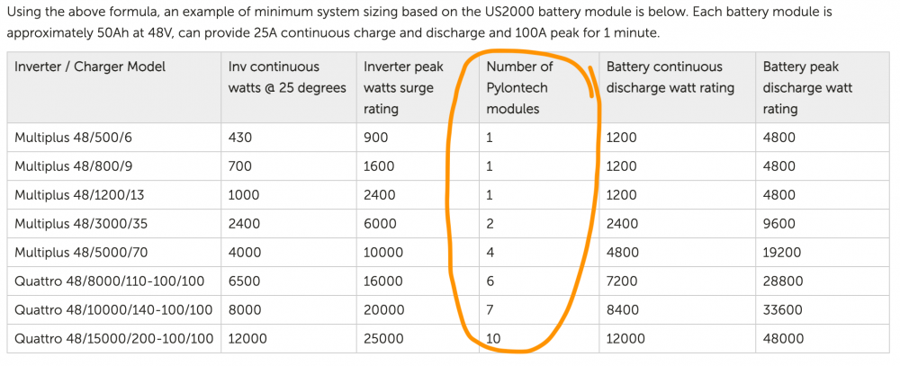
This type of configuration, and specifying the number of battery modules, are normal for all battery bank manufacturers and would be a similar requirement from most inverter manufacturers. You may void both your inverter and battery warrantee if you exceed the specifications as both pieces of equipment may be damaged due to misuse. Do so at your own risk. These are just facts.

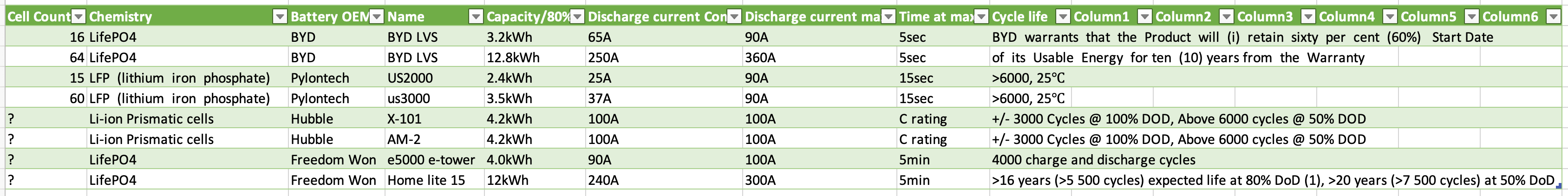
Battery modularity is a good feature. It somewhat ensures future additions to allow expansion of storage capacity. This is not garanteed however. Being able to parallel 48 Volt batteries is desirable. Just some battery comparisons for the local market. All these were available for purchase during the plandemic year of 2021.

80796205_Screenshot2021-10-23at18_11_23.thumb.png.4de1fac39dc441886894ed7090a7f784.png

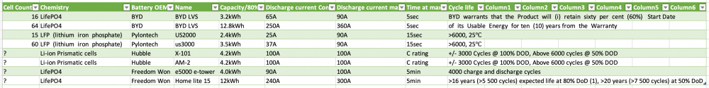
Here you can see a summary for various modules. Theses specs were current at this time, they may be changed at any time.

It is abundantly clear from the above that there are major differences between manufacturers and modules. This is not a recommendation of any kind, merely to show capabilities. Pick a system that firstly can communicate with each other if at all possible, only ignore this as a real last resort. Secondly ensure that minimum specifications are met, this is not optional but required. Your system will have a long happy life, and so will you as your significant other will not attempt murder ;)

Next time:

  1. Based on the previous, plan a system’s PV Panels

PS: my spelling sucks ;)

  1. Based on the previous, plan a system’s PV Panels

Now that you have a grasp on what the overall energy is that you need to generate and what string voltages your inverter can possibly handle, we can start to look at the panel design. Staying within the maximum string voltage is a must, no option here. If we work on an inverter with max string voltage of 450V (500V plus 50V safety margin) and a panel voltage of 50V, we can put 9 panels in series. Be careful of cold winter mornings tho as panel voltage rise as it gets colder. Depending on the inverter max string current per string, you now need to select the panels. You do not want to have much more current per string than the inverter can accept, as that will be wasteful. However, some overcurrent is good on bad weather days or Winter time when you have less hours of Sun available. The over current of the string will help boost output on those low solar days. So it’s a fine balance indeed, the Goldilocks zone.

Next consideration would be physical panel size, installation type and place. Also to consider is half cut cells, and please always go for this. It helps produce more power under partially shaded conditions or cloudy days. So now, depending on the panel Wp numbers, you selected 18 panels (Voltage limited) of a certain size. These must be installed somewhere. Lets say them panels measure 2 M2 equalling 36 square meters surface area. To get to the 7600Wp sizing we need 425W panels. Now the string Voltages are within limits and we can get to our required power levels. The original (see earlier calculation simulation) calculations had 20 x 385Wp panels. These adaptations are to be expected, and desirable as they make for a better system.

If you have a structure with ample roof space to fit the panels, good. If not you have to compromise. Split the two strings to separate roof spaces, use a carport roof or build a ground structure. During all of these deliberations, remember the Azimuth (in SA really North facing or 0Deg, also don’t be fooled by the magnetic declination, account for that) and the panel angle. There are numerous online Web based tools that can simulate things like this. NREL PVWatts calculator being a good example. Fail to plan, plant to fail!

Last point here, when installing your panels, you have this one chance to get the panel orientation and angles right. You pay a little to do so, thereafter the extra energy generated by optimising is essentially free for ever. I did a calculation on a Panel size of 10kWp and the optimisation effort caused a 1000kWh per year boost to the energy generation, for free every year. This can equate to 1 or 2 months work of energy consumption extra!

  1. Plan Inverter and battery systems will be next…
  1. Plan Inverter and battery systems

Inverters ahhhh…. If the panels are the source and generator of energy (those sparkly angry pixies), the inverter is the heart of the system. It pumps the angry pixies where needed. There are, for reasons, many types of inverters on the market. Modular systems, Hybrid systems, Grid-tie, 3 Phase, Integrated systems, Off-grid systems, High Voltage and Low Voltage systems (as to battery voltage) and many besides, each type has it’s advantages but also disadvantages.

The merits of each system type are wholly dependent on your requirements, hence questions…. Once you have an idea on what your requirements are, you can start to look at what is best fit. Always compromises ne…. Your approach to the system will have a big bearing on what type of inverter system is best suited. One type is not always better, just better for YOU. Normally, and broadly speaking, your use case will kind of dictate the system type. You only want load shedding rideout, a UPS can do that, or well a Solar system with no Solar. Whaaattt, Solar system with no Solar??? Yes indeed. Instead of a normal UPS, use a Solar inverter with UPS capability, most all of em, to be a functional UPS.

Reason being, flexibility and future expansion. Life happens, requirements change over time, buy some flexibility on day 1. Hybrid inverters can accommodate Solar panels on the input, have utility grid input, have battery capability and may have an essential load as well as non essential load outputs. They also have varying degrees of monitoring and diverse management functions.

Basics on inverters. There are classes of power for inverters like a 3000Watt (3kW) or 5kW etc class. There are also manufacturers that may specify 800VA or 3kVA. All these are significant as they do not mean exactly the same. If the specs are in Watts, or kW, that is real power. The kVA or VA is a bit more complex, and called apparent power. It’s a current thing. Watt is the unit used for real power while VA is used for apparent power. Real power, or watts, is the power that is actually consumed by the resistive loads like a kettle or geyser. All components have some amount of resistance so each part consumes an amount of real power, frequently the bulk. Apparent power, or VA, is real power combined with the effects of reactive loads like capacitors and inductors, electric motors and other devices. LED lights are normally a “bad or reactive" load in the sense that their PF is far from 1 or really inefficient.

Angry pixie diversion first: There is a reason why we need to distinguish between VA and Watts, and that is efficiency. Watts is the actual power needed to accomplish the job in AC, but the power consumed is the much higher VA. In order to minimise the wasted power, it is necessary to get the VA value as close as possible to the watts value. The ratio between the two is the power factor, and it is desirable to get a power factor of “1” or close to it in order to achieve maximum efficiency. In our homes, we do not have any real options to manage the PF values, well we can, but blue pill red pill. For us its a function of the appliances we run, or combinations thereof. It’s enough to know what the inverter is rated as. The inverter will just deal with the PF and generate real and apparent power . Just be aware that manufacturers can use either method to rate their inverters and them rating are not the same.

Let’s take LED lights as an example here. A LED light with a power factor of .95 would draw approximately 0.092 Amps while the same LED light with a power factor of .55 would draw 0.16 Amps. Therefore, if we had an electrical circuit designed for a 6 Amp circuit breaker, 65 LED fixtures with a 0.95 power factor could be installed as opposed to the 37 LED fixtures with a 0.55 power factor. Altho, as residential consumers, we are not billed on reactive power consumption, it is still energy consumed. On a Solar system with self consumption, the PF will have an influence on how much load the inverter can support. A nameplate 7Watt or 9Watt may not, in some cases, really be 7 or 9Watt due to the low PF number. As an aside, a number of LED light have PF of less than 0.5…. Some do have PF correction build in and a PF of more than 0.9. In my case, I used some Philips HUE led lamps, PF of 0.6 as per the data sheet. I also use some other brand LEDs as part of the Tuya system, PF unknown 😕 likely even worse…

Back to reality: What features are desirable in an inverter? I am leaving out Micro grids for this discussion. An essential and non-essential load output. Having loads on the input has it’s place, but but they will be dead during a blackout with no options. A high capacity for overload (5kW inverter with 50-100% overload for a few seconds) to support oopsies and appliance startup currents. The ability to parallel inverters, either for additional capacity or to support 3Phase installs. Don’t die on me, just hold on for a second or so please Mr inverter.

The ability to upgrade firmware, adding features, but even more importantly, to fix issues. There are lots of evidence, some manufacturers do not update firmware, bugs are around and not being fixed for years. After sales service, enquire from independent sources if that exists at all, the forum here is a good place, search.

The ability to monitor and manage the inverter, remember this is where you control them angry pixies. Data, gimme data. If you cannot measure and see, you cannot manage nor optimise anything. Consider the purchase, if not included in the inverter, of an external or aftermarket monitoring system as mandatory. Also, this is essential to be managing the system remotely. Things happen, so consider remotely managing settings as it’s the only way to manage if you are not home.

You noticed yet that no specific brands are mentioned, and now? There are many, covering all sizes, types and price ranges. Yes there are better quality ones, better engineered ones etc etc and also some made to a price so more affordable. Whatever you do, get one that are bigger than you think, especially if it is your first one. The choice, and budget of course, is yours. What if you get married, or get children or add on to the building? Those things are expensive by themselves ;) no need to add expanding Solar systems on top.

For the purposes of this Utility connected off-grid (its actually an ESS or Energy Storage System, but you can switch the Utility grid off) we have already determined the inverter sizing at 8kW. Remember it’s for the purposes of modelling this system so we can understand how this planning works. Your system capacity may be different. It’s now only the type of inverter and the specifications you need to worry about.

Next be storage, batteries really.

  • Guests

Posted October 29, 2021

Storage, batteries really or angry pixie containment 😕

We can store energy in many forms, as hot water, in gravity by pumping it higher and chemically in fuels and batteries. One thing about storage is conversion, and conversion is lossy. Therefore storage is lossy. You can never take out what you put in, its always less that you can take out. Practically speaking, the only real viable storage medium for residential and most commercial users, are battery storage. We have 2 basic storage types here and that is Lead acid and Lithium types. There are many many more types of batteries, but not really relevant here, for now.

Today, Lithium types rule the roost. Lead acid are still being used, but the life and energy storage can no longer compete with Lithium types. Lead acid is cheap to buy, but life costs really cannot compete at all. Lithium outperforms Lead acid types on all levels. The exact type of Lithium cells for stationary batteries is not that important in the bigger scheme of things. Hence we will leave the chemistry discussions for another time.

Because we are dealing with Residential and Commercial systems mostly, 48Volt systems should be considered the bare minimum. There are 12V and 24V systems on the market, for UPS only style systems, and that is ok. Anything from 2.5-3kW inverters, or whole home or business supply, only consider 48V systems or even higher voltages. There are Low Voltage Inverters and High Voltage inverters. LV is normally 48V nominal and less, where HV systems start from 96Volts and higher. These battery systems are not interchangeable between HV and LV systems.

To power appliances or any load on the inverter we need an energy source. The inverter can either use Solar, Utility grid or batteries to supply the current. Dependent on the loads, the inverter can supply up to it’s max on the output as AC current on standard voltages. To be able to do so, it needs ample current from the source, in this instance, batteries. There are losses everywhere, internal to the batteries, cable connectors, cable crimps and splices as well as the cable itself. Everything has resistance, and the resistance can be observed as heat generated. Yes siree, that is why your cables get hot!

The better the connections and crimps are (quality quality quality) and the better, well thicker, the cables are, the less resistance, the less heat generated and then we have fewer losses. Losses are literally energy converted to heat, but not where you want that heat. Remember we addressed power de-rating of inverters and equipment due to heat? So do not create heat, it reduces performance, and can cause fires in bad cases. Bad connections will do so as well. Battery cable calculator

This is what a 290Amp 48Volt cable looks like, it can handle this at up to a 3 meter length, thereafter you need 90mm square cables. This battery energy is very dangerous, this is no joke. Arc welding is done with low voltage and a few amps to a few 100 Ampere, and that can met all metals. A battery system can easily generate 1000s of Amps at 48 Volts and can easily kill you or burn you very very badly. The energy potential is tremendous.

crimp.thumb.jpg.f4db76625ff2d4ae0eaf58fd6233b5ac.jpg

cable250A.thumb.jpg.90b67c73e027130e45a2bfcc4fa6322d.jpg

250Aconnector1.thumb.jpg.f69b0cf837d217fdb64b2ea0ffefed93.jpg

This is an 8000VA inverter and as can be seen, there are 2 x 70mm square cables on both the + and - feed from the DC busbars. This is good for carrying about 580 Amps or 27-30kW. The bus bars can handle 1000A. This just means, with this inverter, we are not heating the cables by much. Expansion to the second 8kVA inverter on the same bus bars is perfectly catered for. Normal capacity draw for this inverter at full load is 330 Amps from batteries. X2 of them will be 660 Amps continuous. Bursting can be over 1000 Amps for a few seconds. My battery bank, eventually 3 towers, can supply 1170 Amps for 5 seconds, within specs.

10271842_ACtransfercapacity0AInverter220V.thumb.jpg.64ab1f3cf631de8ab9dc204fb19b9d3a.jpg

200800809_Screenshot2021-10-28at13_26_44.thumb.png.9143c9b304574e2ec29976fab06a06f5.png

The BMS charge and discharge current limits, currently two towers with 8kWh ea. As modules gets added, these currents go up.

Them angryy pixies…. You have to satisfy the current demand from the inverter to be able to power the load. You cannot exceed the design capacity of the battery as that can damage it. You will loose your warranty on the battery. Battery BMS systems normally log all errors and trips.

We have shown previously how the calculation works. We also showed how much battery storage you need for a connected but off grid (ESS) situation. What carries you after sunset and during blackouts, are the battery energy. You have but two choices here, reduce the load on the system to last you the required time, or add storage capacity. You can use the Utility grid or a Generator as well, when really needed.

When it gets to battery capacity, we have two choices really, buy into a modular system or buy single on capacity system outright. My crystal ball is distinctly charcoal grey, so the future is kinda not so clear currently. The only certainty for the future is that things will change. Modularity here is like insurance against change that is unexpected. With a modular battery system, you can add capacity any time, within the limits of that specific system. So you can buy budget fitting today, and expand again in future according your budget. No replacement, no selling of the old system or any malarky, just expand.

Included here again for easy reference, some manufacturer specs:

1413710152_CellCountChemistry.thumb.png.00f8a76ddfe0ff57e455a6ed61517c30.png

Next time:

  1. Monitoring and managing the system

250A connector.jpg

Interjection, maintenance and spares…. Got home and noticed my PV charger was off, odd indeed at peak Sun ☀️

Start the investigation. Hmm input voltage is 12V instead of the usual 80-100V. I only noticed this at 14:00 when I got home. Isolate the panels and investigate.

868459CE-4BC1-4991-83C8-3571EDDFBC81.thumb.jpeg.570ba4739c9eb68e6a335234cf747139.jpeg

Switched panels back on, still 12V. Ok switch em off again, tested fuse, blown. Whaddaya know, fuse gone. New fuse, thank you back to normality, yay.

As part of the original plans were spare parts. So spare fuses, spare cables, spare lugs, spare connectors like MC4, spare bootlaces and spare network cables. Test em network cables, I had a few bad new ones recently. It is a tremendous help if you can reach over and grab whatever you need to fix something broken.

  1. Monitoring and managing the system

We can not know what we do not measure, and never will….

That is how important monitoring and measurements are. Insight, understanding and controlling the outcome, all based off of measurements. How do we measure and what should be measured, now that is a good, no very good question. This is not about whatever monitoring program or app. This is about the act of managing and monitoring.

Since we talking a grid tied off grid system here, the inverter and battery bank(s) are of the utmost importance. Understanding and knowing, no not guessing, the status of the various components in the system is vital. That, and only that, will ensure a properly maintained and working system with a long service life. Obviously that means quality components and not some inferior parts like 85DegC capacitors inside the inverter etc.

If we have done everything else right, and are monitoring the system properly, we can ensure that the parameters of the components are not exceeded. It goes without saying. Exceeding any parameter may well damage the equipment. The most fragile part of the system are the batteries. Things like over or under charging them, exceeding the maximum Voltage or Current will destroy them in very short order.

So what, we set them parameters on the inverter and be done. No need to monitor anything…. Most Inverters have the bare minimum of information available, batteries even less so. Components inside the inverter and batteries age, as does any part of the system, even Solar panels do. This ageing causes to components and that in turn can cause measurements to be incorrect over time. Some systems use circuits designed to minimise this ageing effect on measurements. It is expensive to do fancy things like this, but you pay for quality. Not all build in monitoring in all inverters or batteries are created equal, some are less accurate than others, sometimes wildly so. Therefore a secondary monitoring system is sometimes recommended, that also provide redundancy. There are many monitoring options on the market, some specific to an inverter, some generic. This is entirely and subjectively based on your trust level of a product, both the installed solar equipment, as well as the aftermarket monitoring. If you feel you trust the manufacturer, reseller and installer, good, but verify. In the Solar World, unlike say the Marine World, there are no standards for equipment really. Yes there are electrical and house wiring standards, also somewhat applicable to Solar, but no interoperability standards, monitoring standards or standards of installation and inspection. (PS: these are facts, just look at some installations).

Marine equipment are designed to a different and more rigorous and robust level, than say your residential equipment. There are far more stringent testing to be passed. This is just to illustrate that quality and standards do vary. So Caveat Emptor, buyer beware. Do your research prior to jumping in the deep end. Not all resellers and installers are always forthright and totally honest, or even knowledgable.

During this time of the year of the plandemic, where people are at home, monitoring and management is easy, you are right there. Under normal, not plandemic conditions, remote monitoring and management is crucial.

What do you want to manage, is the question. Overall health of the system. As your needs change, and they will change, sometimes on a daily basis, you want to, or should, adjust the system components to satisfy the need and demand. So, changing settings are kinda important. The battery SoC is vital. If you expect a few days, or one day, of bad weather or rain, you may want to ensure the battery is charged. If a blackout is announced, or 2 weeks of, you want to make sure, or at least check and verify, the SoC. You may want to know the load on the system and understand how long the battery will last.

These are the basics. This will give you an idea of what to monitor. At least monitor for them things you want to manage. Data is worth gold, the more you monitor, the better you can mange, especially remotely.

  1. Surge and Lightning protection is next, shockingly so….

On 2021/11/04 at 2:43 PM, Sarel said:

Interjection, maintenance and spares…. Got home and noticed my PV charger was off, odd indeed at peak Sun ☀️

Start the investigation. Hmm input voltage is 12V instead of the usual 80-100V. I only noticed this at 14:00 when I got home. Isolate the panels and investigate.

So my above post was in fact WRONG in it’s conclusion. Ha you say!

Yuuupppp dead wrong. It was a failure of sorts, but rather me planning and oversight failure. Whaddaya mean? So the fuse was not bad as a second one gave up the ghost. This time I caught it immediately. When taking the fuse out if was hot, it burned my fingers 🧐 hot. When purchasing the fuses, the oversight was that of forgetting the the DC coupled system would be configured as 2 x 3 panel strings in parallel for double the Amperes. See was easy as that your fuse becomes to small 🤣 or should that be short…

So the MPPT ramped up the current from the strings and heated up the fuse at the same time, as per the below. At the time of failure, the fuse conducted about 21.5A and had an elevated temp already. No woodier it gave up the ghost, its rated for 1000V at 20A 😆 . New fuses on order. In the meantime, the big ass fan on the fuse holder and MPPT keeping things cooler and the fuse not blown.🙃

1779197657_Screenshot2021-11-09at16_36_14.thumb.png.5690e30d25527a179cdb999767635cd9.png

  1. Surge and Lightning protection, they amount to nothing without Earth…. THOR, the Norse god of thunder, was supposed to be a red-bearded man of tremendous strength, his greatest attribute being his ability to forge thunderbolts.

Earthing is the means that we use to carry away the destructive energy of surges and lightning. There are devices both active and passive, that we use to capture and pass the currents away from people and electrical or electronic systems and conduct them to Earth. It is blindingly obvious, that everything depends on a good Earth.

Lets start with this: Lightning Protection Overview - Lightning Protection Institute Getting a basic understanding in place, it’s a fascinating read anyhow. Also locally we do have standards for lightning protection: Basic Lightning | Lightning Protection

Surges and Lightning, what up with that? Let’s define quickly:

Surges are Voltages and Currents that are created or induced in a distribution system. These are normally of a medium and lower magnitude compared to Lightning. This may be the Electrical distribution system, Communications distribution system or even The PV generation system.

Lightning are a type of surge that can be extremely destructive due to its very high Voltage and Current in a very short duration. It can enter systems by hitting a building or cable system directly, or be induced electromagnetically into many types of systems. This can happen over a wide area as cables and structures act as antenna for the electromagnetic waves.

The main objectives of earthing are as follows :

  • To ensure safety of personnel and property from hazards of electric shock and electric fires.
  • To ensure that system voltages on healthy lines remain within reasonable limits under fault conditions thereby preventing insulation breakdowns.
  • To provide a low impedance path to facilitate the satisfactory operation of protective devices under fault conditions.
  • To minimise arcing burn downs, as in an earthed system, an arcing fault would produce a current in the ground path thereby providing an easy
    means of detecting and tripping against phase to earth arcing fault breakdowns.
  • To provide an equipotential platform on which electronic equipment can operate.
  • To provide an alternative path for induced current and minimise the electrical noise in cables.

There are five elements that need to be in place to provide an effective lightning protection system.

  1. Strike termination devices must be suitable to accept direct lightning attachment and patterned to accept strikes before they reach insulated building materials.
  2. Cable conductors route lightning current over and through the construction, without damage, between strike terminations at the top and the grounding electrode system at the bottom.
  3. The below grade grounding electrode system must efficiently move the lightning to its final destination away from the structure and its contents.
  4. Bonding or the interconnection of the lightning protection system to other internal grounded metallic systems must be accommodated to eliminate the opportunity for lightning to side flash internally.
  5. Finally surge protection devices must be installed at every service entrance to stop the intrusion of lightning from utility lines, and further equalise potential between grounded systems during lightning events.

Lightning protection systems are designed first and foremost as fire protection systems – to stop the building from burning down and losing the people and equipment inside. Bringing metallic services into a structure provides paths for lightning to follow from the outside environment to create hazards within. We bond or interconnect grounds and pipes to the lightning protection system to avoid a portion of this problem. The next step is to provide protection on circuits associated with electrical, communication, and/or data lines that can transmit lightning into a structure. The severest problems are associated with utility service lines that are extensive systems, either pole mounted or buried, that can transmit additional indirect strikes to the building. A complete lightning protection system according to the Standards includes surge protection devices at every entrance of building service conductors, whether they are utility or possibly structure-mounted like an antenna system.

Surge protection devices for building entrances are designed to “ride” the line, sense over voltage problems, and send excessive energy directly to ground. SPDs designed for lightning surges must react quickly to the onset of the sharply rising waveform and be able to sustain the ground connection through the severe over voltage incident, then reset to their monitoring role. Most devices have two or more internal elements to accomplish the task, and react at something around 150% of the standard operating voltage of the system. SPD elements can be thought of as self-sacrificial and may burn out over time protecting against a multitude of small surges (like standard switching surges from power transmission) or a few massive surges like direct lightning attachments.

Therefore it is important to have SPDs accessible for view or to have indicator lights or other identifiers to know your protection continues as designed. Since service entrances for various systems operate at different voltages, SPD components must be individually sized for each system and are generally packaged individually to address specific functions, but if services enter a utility room for distribution throughout the building in a common area a single SPD may be designed to serve several functions in one housing. Since adding ground path length only serves to slow the reaction time of SPD components, the SPD device should be connected as directly to the grounding system as possible always with minimum lead length. You always want the lowest resistance to earth.

So then, another rabbit hole is facing you, types of surge protection. Lemme make that easy:

1079380226_Screenshot2021-11-16at09_33_03.thumb.png.16101040284e6ba7e9e6f479df9153e4.png

Selecting the correct SPD is not so easy. Ensure understanding before selecting. There are lots of good info on the interwebs. By the very nature of the potential energy and duration as well as point of entry into your home, you need to select different types of SPDs. Now we have 3 main types of incoming paths.

  1. PV Panels
  2. Utility mains
  3. Communications

Each one of these requires a different type of SPD because the Voltages are different, both in type as well as magnitude. PV panel strings can generate 1000VDC while the Utility grid is a nominal 240VAC and communications can be Fiberoptic or low voltage high bandwidth signals.

As stated earlier, the efficacy of the SPD is ENTIRELY dependent on the quality of the Earth connection. There are devices that can be installed inside the DB to monitor and report on this. Or, you can have Sparky measure your earth. That is a one time deal however and we do not know the changes over time until measured again.

512328243_Screenshot2021-11-16at09_35_47.thumb.png.747f2f2b95e221051f895f668dec0fc0.png

This is the minimum automated way to be sure, and not guess, that your Earth is good. We can only manage what we can measure. We have all done it, but just hammering a Earth rod into the ground is no guarantee that you have a good Earth. We simply do not know id the Utility supplied earth is any good either.

Next more on Lightning.

SALDN lightning statistics since Nov 2005 for South Africa.

  • Total 65 million strokes
  • Average per annum = 24,7 million strokes
  • Summer season 06/07 (Oct to Apr) – 21,5 million strokes

These are maps for Africa and South Africa

africastrikemap.thumb.jpg.c6a4cb30332ee785e08034eb1456d9a9.jpg

rsastrikesmap.thumb.jpg.acd0990dc598db49586fd056388e1260.jpg

Some parts have more risk than others and that risk changes seasonally.

Categories of surge protective devices

Surge protective devices are categorised as lightning current arresters, surge arresters and combined arresters.

The highest requirements are placed on the discharge capacity of lightning current arresters and combined arresters used at the transition from lightning protection zone 0A to 1 or 0A to 2. See below. These arresters must be capable of conducting partial lightning currents of 10/350 μs wave form without being destroyed in order to prevent the ingress of destructive partial lightning currents into the electrical installation of a building.

At the transition point from LPZ 0B to 1 or downstream of the lightning current arrester at the transition point from LPZ 1 to 2 and higher, surge arresters are used to protect against surges. Their task is both to reduce the residual energy of the upstream protection stages even further and to limit the surges induced or generated in the installation itself.

Protection of structures with electrical and electronic systems in accordance with IEC 62305-4

  • LPZ 0A Zone where the threat is due to the direct lightning flash and the full lightning electromagnetic field. The internal systems may be subjected to full lightning surge current.
  • LPZ 0B Zone protected against direct lightning flashes but where the threat is the full lightning electromagnetic field. The internal systems may be subjected to partial lightning surge currents.
  • LPZ 1 Zone where the surge current is limited by current sharing and by SPDs at the boundary. Spatial shielding may attenuate the lightning electromagnetic field.
  • LPZ 2 Zone where the surge current may be further limited by current sharing and by additional SPDs at the boundary. Additional spatial shielding may be used to further attenuate the lightning electromagnetic field.

549686036_Definingthelightningprotectionzones.thumb.jpeg.10873fb6ffa184c0f1c28f173e26e436.jpeg

You need to ensure that all conductive routes into the building are protected.

:+1:
If anyone is wondering why there is not just an easy one size fits all option/answer when you get to PV, then this comprehensive planning guides that @Sarel.Wagner gives in this thread in the reason.
This might also be the reason it took me more than 6 months of planning and reading to start my solar. It’s not a quick weekend job like a UPS.

5 posts were merged into an existing topic: Installer Recommendations

This has now been a while since the last post on here. I have been waiting on my own system, described on another thread on here, to mature a bit. It has been 10 months since commissioning that latest system.

A few items remain to be addressed:

  • Tweaking (you always do this even if you don’t want to)
  • Maintenance.
  • Upgrades and additions

So then these would be next.

Groetnis