I have a Sunsynk 5 kW at the Sunsynk repair center in Randburg, one of the things that they want me to do, when I get the inverter back is to do a permanent bond between neutral and earth, something to do with all the load shedding we are having, and the neutral earth relay being a failure point and the client not knowing about it and there might be a floating neutral
That is probably good advice.
Cable theft seems rife during load-shedding, which could result in what you describe.
Uuuuuh… where do they want this, on the output, right? Given that it involves the bonding relay, they know that is not SANS compliant, right?
The fact that the Victron inverters do a bonding relay test suddenly seems like an important little detail init? ![]()
3 Likes
Yes, correct on the LOAD side.
When i sent in the inverter for repairs, they specifically asked me to send pics of the neutral-earth bonding relay, then I was told by no other than Jean ( think he is the big cheese for South Africa ), to permanently bond it. I have heard thru the grapevine that there is talk amongst SANS people and even CoCt sseg people, although, no confirmation regarding this .
Please correct me if I am wrong (that invitation is open to anyone), because I don’t know these inverters that well (or at all), but… ![]() … as I understand it, the Sunsynk/Dye inverters didn’t initially come with a bonding relay. They did however have a built-in general purpose relay.
… as I understand it, the Sunsynk/Dye inverters didn’t initially come with a bonding relay. They did however have a built-in general purpose relay.
A firmware change was then done so that this relay can be switched when the inverter islands. That is, if I remember the history correctly.
This relay isn’t suitable for directly bonding TN, so you use this relay to close an external contactor that does the actual bonding. Again, in the two installations I’ve seen, there was a separate bonding contactor mounted.
If I understand your report correctly, there has been problems with the “bonding relay”, which I take as meaning that internal general purpose relay that was repurposed for bonding, occasionally fails and that leaves the TN bond open.
If I have to make some guesses on top of that, given that even small cheap relays are generally good for a million operations, would it be inaccurate to say that there might be a QA fail here? There are a batch of bad relays that fail early, but it only shows up where the relay is actually used?
If my musings are correct, then top of the fact that the bonding relay is not tested (I don’t know if NRS097, or even VDE 4105 requires that relay to be tested), instead of replacing the failing relays, they recommend a workaround?
I think what I would rather do (in this case) is have my own device that makes a noise if there is a sufficiently high voltage between T and N. Doesn’t have to be very sophisticated, all it has to do is beep when there is voltage there. It will beep briefly when the power goes out and comes back in, or permanently if the relay is broke…
Here is a link to an older version of the Sunsynk NRS report:
There is no reference to neutral bonding.
I did find this quite interesting:
4.16 EARTHING
Installations with utility-interconnected inverters without simple separation shall make use of earth
leakage protection which are able to respond to d.c. fault currents including smooth d.c. fault currents
(i.e. without zero crossings) according to IEC 62109-2.
This would mean the vast majority of installations are not compliant, as I don’t think I have ever seen a standard residential installation with a type B RCD on the output of the inverter.
3 Likes
They have internal GFDI to meet this requirement.
EDIT: Not so - see below…
You are correct. A Type B earth leakage is required for HF inverters unless the manufacturer specifically states that their design galvanically isolates the PV DC side from the AC side.
The only manufacturer that I have been able to find that does this is SMA.
I recently advised an installer chapter and verse about this requirement:
He agreed with me it was necessary.
Then said he couldn’t find one to buy in SA, so I supplied him with a link.
He then said he couldn’t fit them at that price because no one else did, and he couldn’t remain competitive if he included the cost of a Type B.
If you delve into the SANS compliance documentation from other approved inverters ( like, say, Solis) you will also find this same caveat.
Robin ( test equipment manufacturer) actually patented an earth loop impedance tester that could test the earth loop impedance live without tripping the standard Type AC earth leakage protection by defeating it by injecting a DC component. So yes, it is essential to have a Type B.
This isn’t my understanding of Sunsynk’s recommendations. I understand the inverter will provide a contact that operates when the grid AC is lost. Sunsynk then advises that this contact, in turn, can be used to drive an unsupplied heavier-rated relay/contactor ( that an electrician would fit) that will connect Earth and Neutral.
Some installers forgo this and permanently bond the Neutral and the Earth.
1 Like
I was installing contactors, but as I understand it, Sunsynk “South Africa” now wants us to permanently bond neutral-earth on the output.
Is the internal ground fault monitoring sufficient though?
Fronius (for example) has an RCMU that does something similar, but it needs 300mA continuous or an sudden change of at least 30mA to trigger. This complies with IEC 62109-2. @Phil.g00 , that’s good enough, right?
For funzies, I looked up the spec sheet for my ancient ABB DM PV-inverter. That doesn’t mention the IEC standard, but it does list identical behaviour:
- If IDIF > 300 mA for a period of 300 msec
- If ΔIDIF/Δt > 30 mA/sec for a duration of 300 msec
- If ΔIDIF/Δt > 60 mA/sec with duration of 150 msec
- If ΔIDIF/Δt > 150 mA/sec with duration of 40 msec
If I understand Tarique correctly, they are now advising a permanent bond, because…
By which I assume they mean the small internal one, not the external one switched by it.
That is a problem because…
… which suggests to me there is also no relay test for this particular relay. Which makes total sense if it is a general purpose relay that was repurposed (in firmware) for this task… hence my speculating about it ![]()
Oops internal Type B GFDI is only on the DC side.
This requirement is specific to:
4.2.6.2 Installations with utility-interconnected inverters without simple separation shall make use of
earth leakage protection which are able to respond to d.c. fault currents including smooth d.c. fault
currents (i.e. without zero crossings) according to IEC 62109-2 unless the inverter can exclude the
occurrence of d.c. earth fault currents on any phase, neutral or earth connection through its circuit
design. This function may be internal or external to the inverter.
All HF inverter designs could potentially result in DC output on the grid terminals. It could probably be eliminated by separate watchdogs or passive DC crowbars, but I am not aware of any HF inverter that does this.
So, I suppose, technically, all HF inverter installations require a type B RCD. Oops…
1 Like
Yes this was something Phil raised a while back, but we assumed that no one really complies with it else the HF “cost” advantage over “LF Victron” would not look so rosy.
1 Like
I don’t have the IEC 62109-2 text, so I can’t answer this from a lawyer’s perspective.
Quite frankly, I don’t care if it is legal if it is unsafe.
On that front, I can provide insight from a technical perspective, and you can make your own mind up if it ticks the boxes.
Type B E/L trips at low constant ( smooth) DC earth leakage levels.
A Type B earth leakage is specified to trip with a 6mA DC-to-earth current threshold as well as the normal 30mA AC-to-earth current threshold.
The AC trip thresholds are based on empirical research on lethal levels of current.
That is not the same rationale behind the DC trip threshold.
6mA DC is not lethal.
But at 6mA of DC, the CT core in other E/L types will magnetically saturate, rendering them blind to potentially lethal AC faults.
Now do these inverters in question trip (not alarm) at this level of DC on their AC side?
1 Like
I think that’s what we concluded last time as well (but I forgot somewhat). Yes, these inverters trip and raise an alarm if you exceed the limits, but as noted… it can leak 300mA continuously without tripping, as long as it’s a stable leak ![]()
It does make me wonder what the point of the IEC standard is then, if it is not good enough.
For interest sake, here is the paperwork for a Symo. It references the older German code (0126 rather than 4105).
This is all because of 1 person that is VERY vocal on the Sunsynk Users group on Facebook.
If you look at SANS10142-1-2 (retracted), you will see they are very CLEAR, a bonding relay/contactor shall be used.
They are wrong, even if you look at SANS10142-1, it states in the section for alternative supplies that it 7.12 DOES NOT apply to supplies acting in parallel with the main supply. (It is in the notes, and I am paraphrasing)
My main question always is, what is the NORMAL operational mode? In this case, it is (still) with the grid. Thus the parallel connection to the main supply.
If you are concerned about device failure, be concerned about the Earth Leakage and DC current injection, be concerned about faulty earth leakages in general, or the change-over switch burning down. All equipment can fail, but it is the installer’s responsibility to make sure that it is correctly sized and installed.
A few options to make contactor safe again:
- Add a light between Neutral/Earth, if that light EVER comes on then the contactor has failed.
- Make sure that the contactor is one with an indication when activated (pulled-in button, red/green indicator) and add the contactor where it is visible (NOT IN THE Cable Cabinet of the inverter!!)
- Stop buying Sunsynk until they install an E/N relay with feedback… Like Victron
- Start beating VIctron until they become more affordable, install Victron…
Why you might ask should a contactor be used? (I am busy with a write-up and will build on it as time allows)
Having multiple Earth-Neutral bonds in an electrical system can create several risks and issues. The Earth-Neutral bond is typically made at a single point, often at the main service panel or distribution board, to provide a reference point for the electrical system and ensure safety. When multiple Earth-Neutral bonds are present in a system, it can lead to the following problems:
Circulating currents: Multiple Earth-Neutral bonds can create parallel paths for current to flow between the neutral conductor and the earth (ground) conductor. This can lead to circulating currents, which can cause overheating of conductors, increased energy consumption, and potential damage to the electrical system components.
Compromised fault protection: In case of a fault, multiple Earth-Neutral bonds can cause fault current to be distributed through multiple paths, which may not be detected by the overcurrent protection devices like circuit breakers and fuses. This can result in the devices not operating as intended, leaving the fault undetected and posing a risk of electrical shock or fire.
Voltage differences: Multiple Earth-Neutral bonds can lead to voltage differences between various parts of the electrical system, which may result in unbalanced voltages, equipment malfunction, or increased risk of electric shock.
Electrolytic corrosion: In the presence of multiple Earth-Neutral bonds, stray currents can flow through metallic structures like water pipes, causing electrolytic corrosion and reducing the service life of these structures.
To maintain a safe and reliable electrical system, it is essential to have a single Earth-Neutral bond point, as specified by the relevant electrical installation standard. This ensures that fault currents are correctly directed to the earth, overcurrent protection devices operate as intended, and voltage levels in the system remain stable.
5 Likes
I literally wipped out my old copy of 10142 and found the part you refer to.
NOTE 2: This part of SANS 10142 does not cover the supply to an installation that functions in parallel with the main supply (co-generation).
That talks about co-generation. In our context, that is for PV-inverters, things that work with the grid. Your Sunsynk inverter is essentially a PV-inverter, with a battery inverter in the same box (true hybrid). That note does not apply the moment you are islanded. Then you are an alternative supply, no longer a co-generator. Which is essentially what you said somewhat more eloquently than I can ![]()
I wouldn’t consider this as a Type B equivalent.
Earth leakage protection has had to adapt to the prevailing technology, which has changed considerably in the last 60 years.
When everything was AC type AC E/L was adequate, then along came semiconductors putting rectifiers, diodes and thyristors all over the loads, and the shortfalls of Type AC became evident. So Type A E/L was born.
Relatively recently, along came VFDs and HF inverters. The shortfalls of Type A became evident, and Type B was born. I don’t know the exact timeline, but the solution would have been in response to the problems. Not the other way around.
So I could see that initial regulations may have been inadequate.
A Type AC earth leakage is useless at values well below 30mA of DC leakage. I will go into a bit of detail about why this is.
As you know, a Type AC E/L is a form of differential protection. What goes in must come out. This is easily achieved by putting both the L & N conductors through the same CT. The nett magnetic effect if both currents are equal is zero. This is because the L & N currents are out of phase by flowing in opposite directions.
When there is a disparity between the magnitudes of the L & N currents, this CT produces an AC output proportional to the current disparity. The trip mechanism operates when this output exceeds a value representing 30mA of the primary current.
It can do this because the symmetry of a sine wave results in a nett zero magnetic residual flux build-up in the magnetic core of the CT.
Because the current sine wave is symmetrical around the zero crossing axis.
Sort of a what flux goes up, all comes down arrangement.
If there is a DC offset on the AC wave, the sine wave is no longer symmetrical around the zero crossing. A slight offset builds up the residual flux in the core until it is saturated.
6mA DC is deemed sufficient to saturate the core over time.
This is where some of what goes up doesn’t all come down.
This residual or remanent flux increments over time until the CT core saturates
When the saturation point is reached, a CT loses its magnetic capabilities and can no longer provide an output to the trip mechanism of the protection.
You could have a 100A AC or DC earth fault at this stage, and the protection will not operate.
As an aside, once a CT magnetic core is saturated, it remains saturated even when the power is switched back on and the DC component is no longer present ( for weeks or months, the natural decay is glacially slow).
5 Likes
Adding another separate reply. I think we covered this before. There is a lot of confusion that comes in with sections 7.12.3.1.2 (which seems to allow these multiple bonds):
Where alternative supplies are installed remotely from the installation, or from one another, and where it is not possible to make use of a single neutral bar which is earthed, the neutral of each unit shall be earthed at the unit and these points shall be bonded to the consumer’s earth terminal.
But they miss the second half of it.
The supply from each unit which supplies the installation or part of the installation, shall be switched by means of a switch that breaks all live conductors operating substantially together (see annex S), to disconnect the earthed neutral point from the installation neutral when the alternative supply is not connected.
It is pretty clear that they don’t want two TN bonds at the same time.
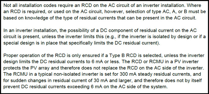
on the topic of RCD (types) and RCMU in PV systems this probably qualifies as a “…for dummies” version that even I could follow. Summary
Not particularly action packed (and muting sound advised) but video of IEC 62109-2 residual current test (which also gives clues to the actual standards). [Residual current test demonstration - IEC 62109-2 - YouTube]
1 Like