As many know I am a fan of contactors over Mosfets.
I am also in the market for a very high current capacity BMS.
Now @TheTerribleTriplet had a candidate that ticked many boxes…
But it didn’t differentiate between charging and discharging, it had one contactor that switched off both charging and discharging simultaneously.
For example, for a battery overvoltage condition, the battery would be switched out when really charging should have been stopped and discharging allowed to continue.
The corollary is desired for an under-voltage condition.
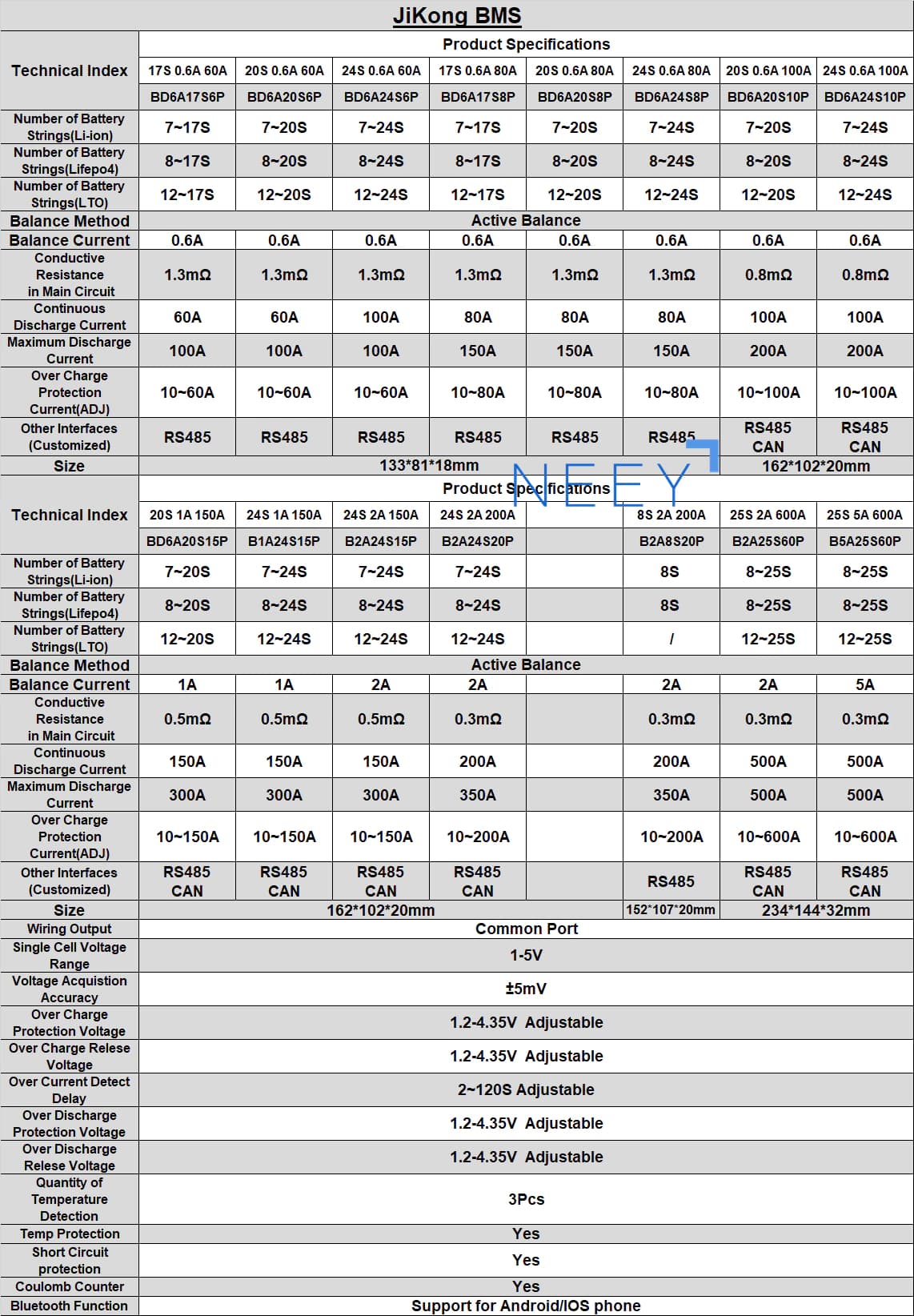
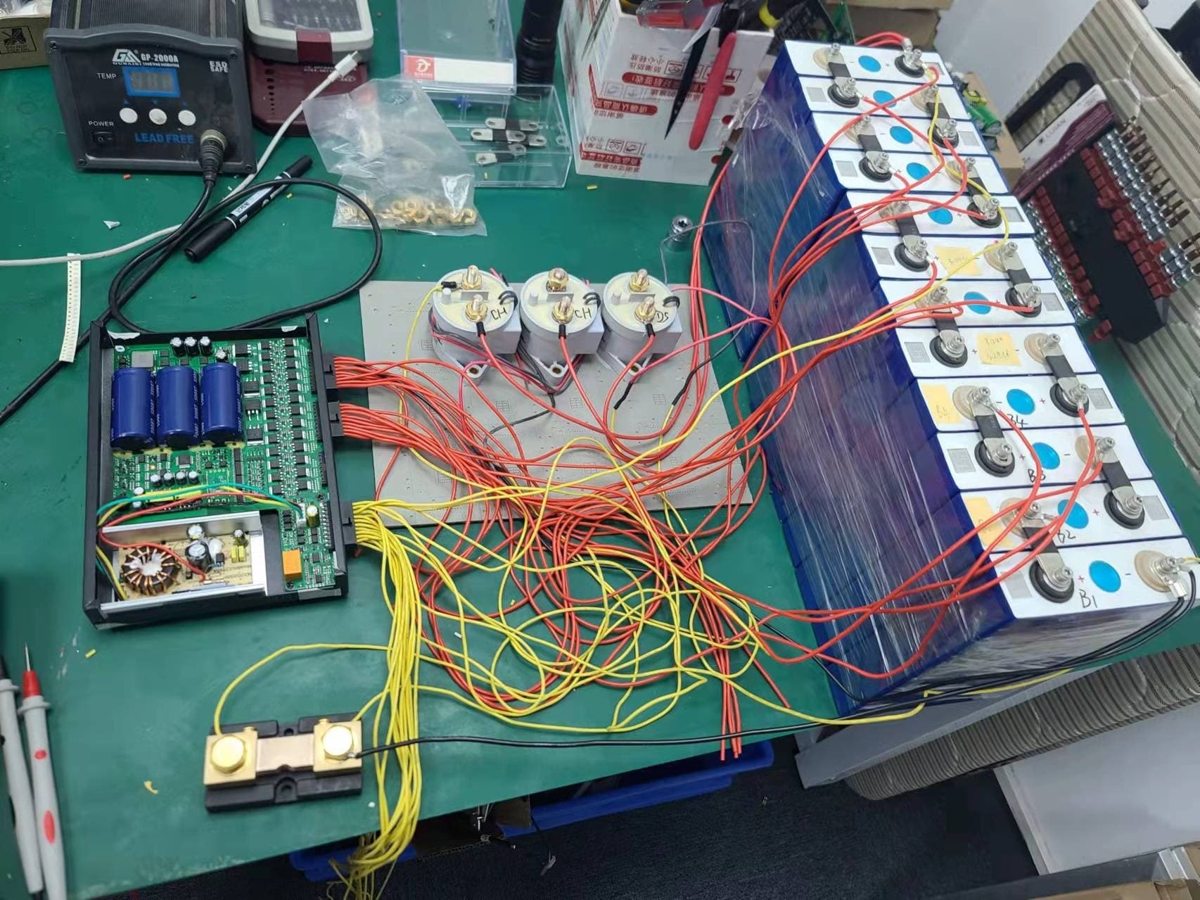
JK BMS has now introduced a BMS with 2A or 5A active balancing, that has an external shunt and can control 3 external contactors independently.
Pre-charge
Charge
Discharge
It has BT IOS/Android app, CAN and RS485 ports, temp. probes etc.
It is rated continuous at 500A, but I think that is just a shunt and contactor limitation. These are all external so could be potentially exchanged for higher current doodads.
( caveat: I don’t know what the app limitations are above 500A- looks like 600A max setting).
Typically balance leads all have to be the same length, this BMS allows the balance leads to be resistance calibrated. So balance cable wiring management is improved.
This is where I’m at:
I’m watching Andy and waiting for him to finish his tests … as he has had cases where he was very happy with a product, and then things went south.
Also, the price and the fact that as per Plonkster, which makes sense, the active balancing on good cells, can be a bit of a waste.
I find that helping the BMS with 1) the charge amps based on SOC and 2) the max voltage one goes to, like 3.45v, which is also for longevity, and 3) A Grade Batch Matched cells goes a hell of a long way at THIS point of my “book”.
Edit: So, the separate charge/discharge is currently on the back-burner for me, as it has its own set of unique challenges, now that I’ve tried other ways to avert it happening at nearly all costs.
Someone said, forgot who, let the equipment handle it, fewer parts and less stuff than can go wrong.
Once he is using it in production, I will wait a few months for his verdict:
When he got it:
I saw a part in one of his videos using similar contactors and there was a “challenge”. Will see if I can find it again.
Looks good. Just remember that the separate contactors only really works if you have a separate charger/inverter. Also you don’t need a big relay for precharge.
(I am a big fan of MOSFETs - but they need to be properly protected and oversized so much that no heatsinking is required)
It’s a bit difficult to disable only charge or discharge with contactors. Of course you could connect your MPPTs via the charge contactor, but your inverter is capable of both charging and discharging, so what do you do then?
True, this one has no track record, I think it has just been offered.
As to active balancing that is fair comment as well, I wouldn’t pay the premium for 5A active balancing.
In one of Andy’s vids I saw he ran into the SAME problem I had i.e. me on 280mA and him on a 5amp active balancer. On big ah banks/cells, it is but a drop in the bucket.
Then you’d probably look at a Schottky diode, because a normal silicon diode has around 0.6V drop and that would make a lot of heat on the other side of 100A. A Schottky will still drop 0.3V to 0.4V, so then a MOSFET is no longer the bad guy it used to be. It’s about on par.
I often end up just using a FET as a diode. Just short the gate to the source and you have a diode that can handle hundreds of amps if you can keep it cool.
It certainly does. I often use FETs that are rated for hundreds of amps. Of course you never actually use them at their rated current because the losses would be too high and they would get hot, so you end up using several in parallel even though 1 or 2 could handle the current in theory.
Sure it works, but you are only using the body diode, which is usually not a great diode by any measure. MOSFET current ratings are in many cases limited by dissipation, which is determined by the RDSon for the FET, but you have a voltage drop for the body diode. So you need to parallel quite a lot more of them.
He’s using the “body diode” (which isn’t really a diode at all if you want to be pedantic, but works that way). Shorting the gate to source leaves the FET turned off, so it becomes directional (otherwise it conducts in both directions).
I am not an electronic engineer, but as I understand there are some caveats. The one is that the path through the body diode has a higher impedance, so you do make a bit more heat. The other is that not all FETs are completely “off” when you short G to S. Some have a leakage current. In fact, I’ve seen circuits where the leakage current of a FET (which is fairly constant) is used as a constant current source…