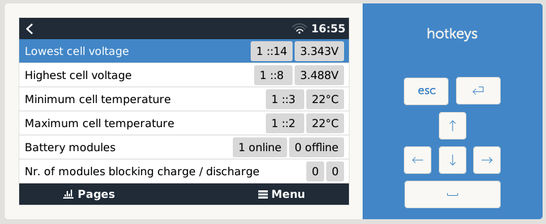
This is completely normal. You will always see one cell jump out as the battery reaches 100%, that’s just how LFP batteries work.
What you want to see, is that the difference between your lowest and highest cells shrink over time. Your lowest cells, of which you have at least 3 if I recall, should move up a little bit every day.
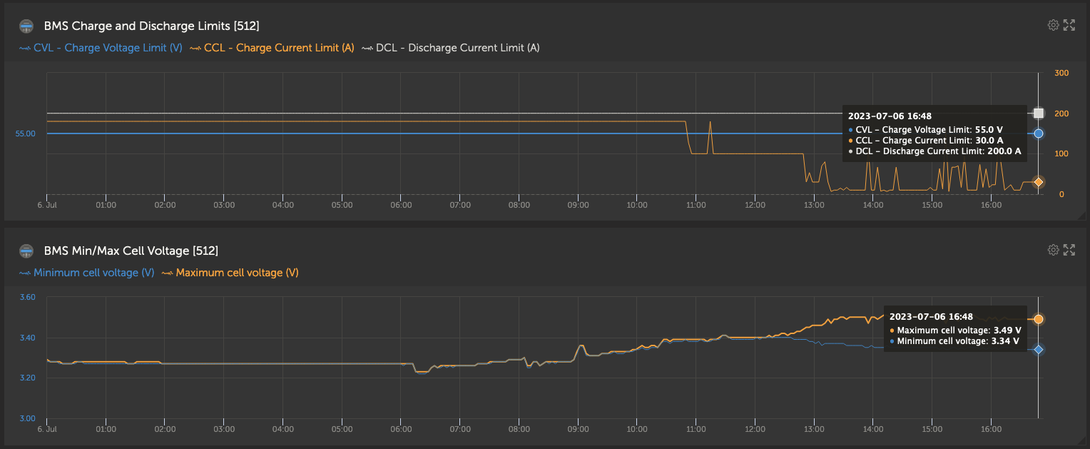
Now think about this mathematically. If all the cells are perfectly balanced, then a 16 cell battery can be taken to 56V without any problems. That is 3.5V per cell.
In reality, what is going to happen is 15 cells will be at 3.45V (that’s over 99% full), and the 16th one will start complaining at 3.6V, making it impossible to reach even 55.4V. A battery in this condition is still perfectly healthy and happy, and about 99% full. There is very little additional capacity above 3.45V.
Over time, you should see that lowest voltage creep up to above 3.4V, and then per definition you will be able to “fit” the full charge voltage in, since 3.4V times 16 cells is 54.5V. It is just a matter of time.
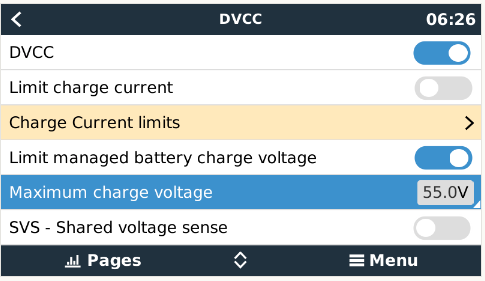
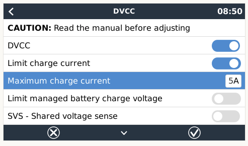
That’s why we have this setting:
You can lower the charge voltage of the battery to one that avoids the problem. You will typically increase that voltage by 100mV every few days, until you can disable it again. Start with 54.5V.
Your case isn’t even that bad. I had a BYD Premium battery some years ago that was particularly bad, it had one very low cell, and one very high cell. Took weeks to get it balanced. Today it’s a happy camper with nary a sign of its childhood maladies.
Some more information.
The flip side of not seeing the imbalance and assisting the BMS to get it right, as per Plonkster, is a potential DC Ripple when the BMS has to disconnect the battery because a cell exceeded 3.65v.
This is specific to Victron, the DC Ripple, due to the LF inverters, I’m told.
The same happens on HF inverters, but no one is aware of it as it is a blip, the batt just switches off.
The biggest component at risk is the MPPT. Victron inverters give a warning, and will disconnect itself. The MPPT not so much.
It tends to happen at high SOC, above 95%.
Possible solution:
Give users a warning of the potential Delta exceeding set parameters, where cell data is available.
Would simply be great that if the Delta exceeds a pre-set parameter, 0.100v for example, the system auto-reduces the max charge volts/amps, to assist the BMS to balance the cells faster.
Then, if that does not work, a cell hits set a parameter, i.e. 3.60v, stop the charging completely until there is a draw again.
The implications of these auto changes on the performance of the system are considerable, but what is worse, the system has to stop operating, batt taken in, versus limp along until the problem is handled by the BMS, the user being aware of the why?
The data is there, the software is developed, just need to make it clever.
Bottom line.
Same as with lead acid, Lithium banks also need some TLC in checking the Delta, the difference between Min and Max cells, or the graph under advanced.
DC ripple is a side effect of having too little battery on the DC side, and it affects Low Frequency designs more. When the BMS needs to protect the battery, and it disconnects from the DC bus, you by definition have too little battery (you have nothing) and all manner of warnings and alarms show up, usually DC ripple, low voltage, high voltage, you name it.
But in this context, the battery is a BSL. Every module runs its own BMS, and every module disconnects from the DC bus, theoretically leaving the other good modules to hold the fort. Of course this only works if you have multiple modules.
The BSL also directionally blocks charge and discharge, so the issues that result from a disconnection are a lot less severe.
Side effect … … it is a cluster when the batt has to switch off.
The fact that it happens, Victron having developing protections for it is GREAT! Gives you a heads-up, whatever the cause.
And yes, multiple batt modules help a LOT, charge/discharge split another level of protection.
But the fact remains that the documentation on that is quite substantial as I learned after the event … as people only become aware of it when they hit the issue, for whatever reason. Or like a 250/100 blows because of that, and it is not a warranty issue. Then it gets rather serious.
So as you know it is a common issue, rather people know about it, and take the necessary precautions, as in the documentation, the lithium BMS’es just a new angle to know of, than try to make out that I’m “obsessed”.
As I said, it is a great “feature” that Victron warns about it, and handles it. Then one can fix the cause, whatever it is.
EDIT:
BMSs are another CAUSE for a potential DC Ripple … the DC Ripple warning your heads-up, in some cases, of a lithium cell imbalance … depending on how your system is set up.
I had a similar issue with my FreedomWon ETowers. Added a second battery and it jus would not top balance. Their solution was to drop the batteries down to 10% and hold it there for a few hours. Solved all my issues.
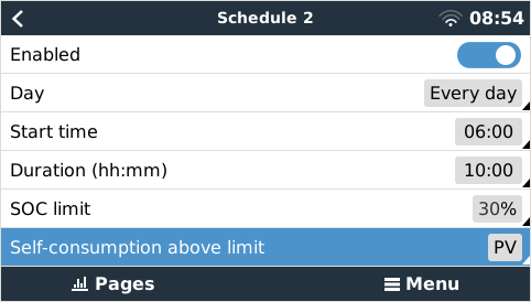
I know it’s still not exactly what you’re looking for, but you can play with the scheduled charge settings and set it so that you only use PV for self-consumption during the ‘charge’ window.
An idea is to have a scheduled charge window for most of the sunny part of the day. Like 6am until 4pm, but with a low SOC limit. Yours seem to be 30% in ESS, so let’s go with that. Then set the Self-consumption above limit to PV and not PV & Battery.
This way it won’t use the grid to charge the battery as it won’t charge from the grid if the battery is at 30%+, but it also won’t use the battery to power the loads if there’s not enough PV (it’ll use the grid for that). So any excess PV not being used goes to the battery as normal, but if there’s a shortage of PV it won’t use the battery, so you won’t have the 30% to 33% charge, 33% to 30% discharge etc. and will prioritize getting the battery full so to say. Once 4pm comes it goes back to normal and will use PV & battery to power the loads until the SOC set in ESS is reached.
It also works along with Optimized (with BatteryLife), so if you have your Minimum SOC in ESS set to 30%, but don’t reach a high SOC, the algorithm will still shift the Active SOC limit and the scheduled charge window will make sure that the battery is not used during that time to further help out.
It’s still not the ‘all PV must go to the battery until the battery is at 100%’ that you’re looking for, but it is an easy way to not use the battery during the day (unless the grid fails of course).
Edit:
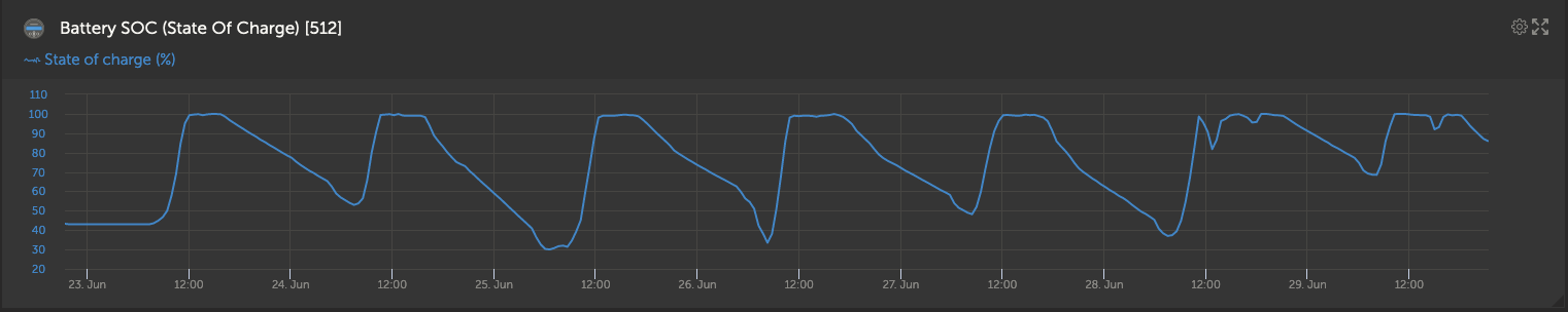
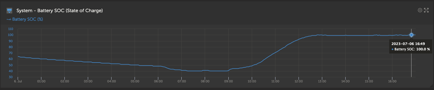
To give you an idea of what it will do when a larger load kicks in:
I’ll be the first to say that I don’t know enough to make an informed opinion, but it doesn’t look too bad to me. The ~0.15V difference is not ideal, but as it jumps out at 99%/100% I don’t think it’s too bad and it should get better with time as the balancer/s brings them closer together.
I can’t remember all the suggestions I’ve read over the years, but if you want to manually intervene (I don’t think it’s needed though) I think @plonkster’s suggestion of dropping the charge voltage to one that doesn’t cause this issue is a good start and then slowly increasing it: